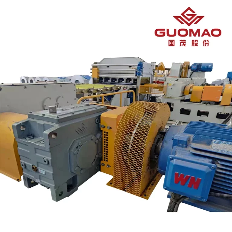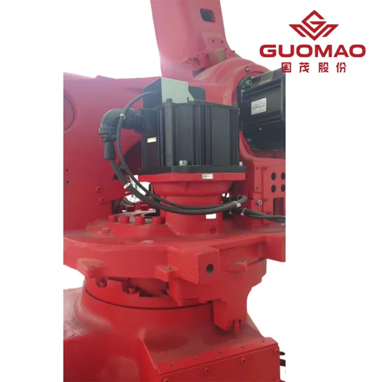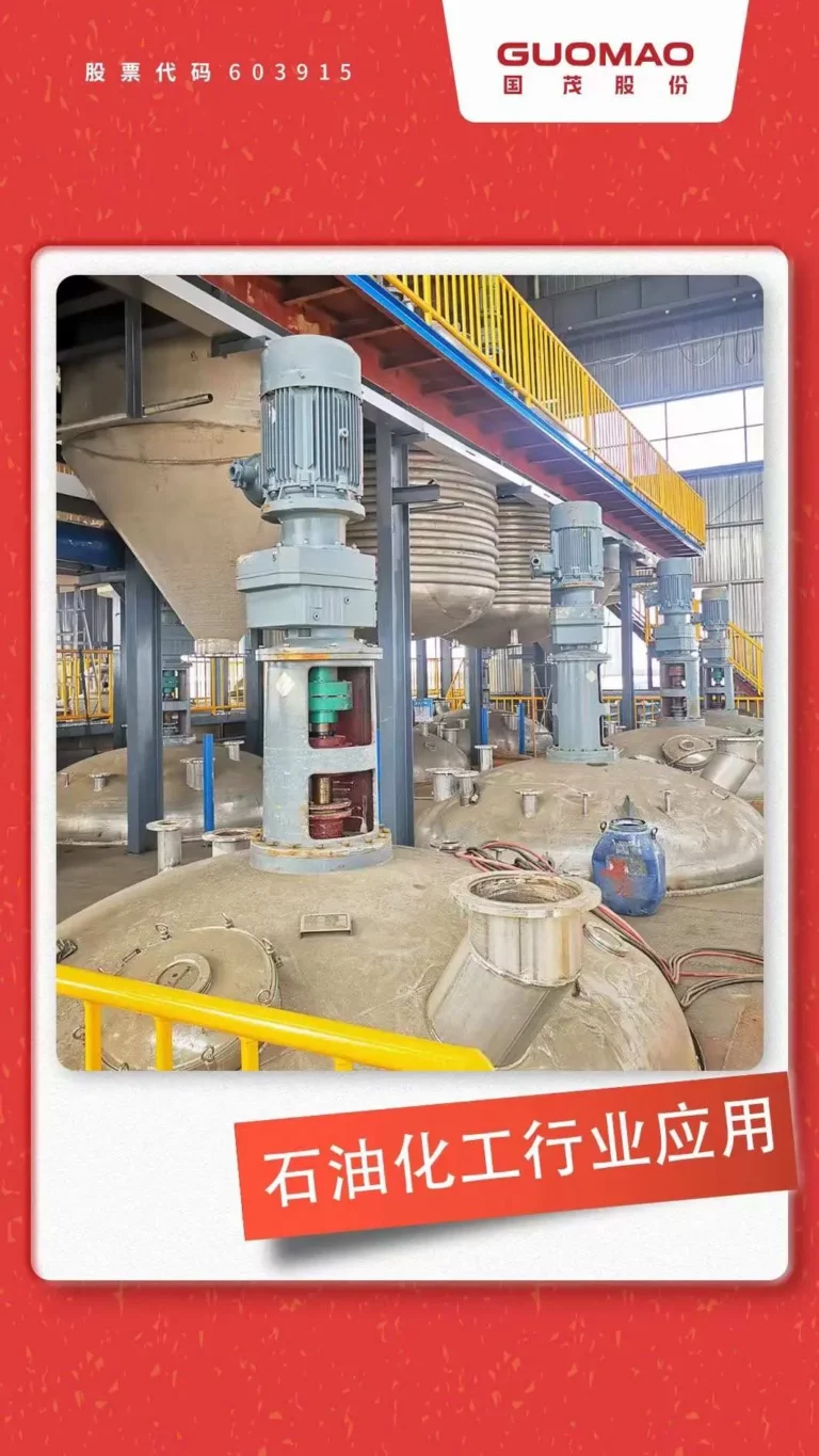



Continuous-duty equipment asks more of a reducer than producing the required ratio. It must transmit torque, hold output speed, control heat, and preserve gears and bearings. Performance therefore depends on mechanical rating, thermal capacity, lubrication, installation, and the real load spectrum.
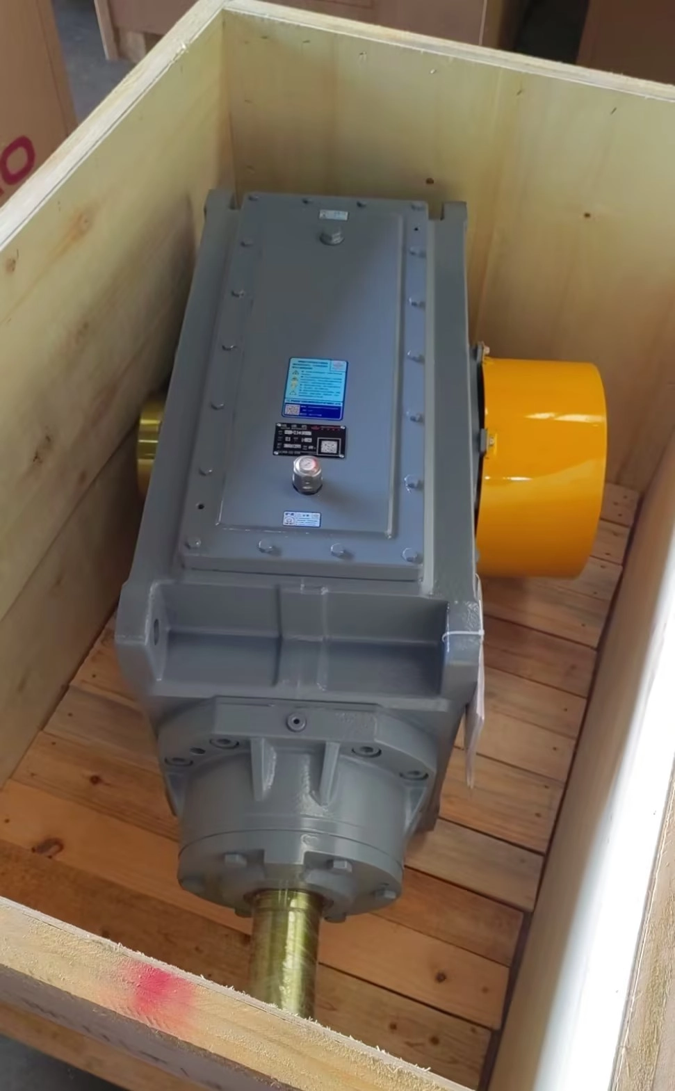
What Defines Industrial Gear Reducer Performance in Continuous-Duty Equipment?
Continuous Torque Transmission and Output Speed Stability
The continuous torque capability should suit the speed and ratio of operation. The motor current, output speed, and load should stabilize into a consistent range; any tendency to drift could mean overload or friction problems.
Mechanical Efficiency Under Sustained Operating Loads
Efficiency divides input power between useful output and heat. It varies with gear geometry, stages, lubricant viscosity, speed, load, bearings, and seals, so use manufacturer data for the actual operating point.
Thermal Stability During Extended Operating Hours
A reducer is thermally stable when heat generation and dissipation reach equilibrium within permitted temperatures. Ambient temperature, airflow, mounting, oil quantity, and cooling affect that balance; continuing temperature rise requires investigation.
Gear and Bearing Durability Over Long Duty Cycles
Long duty cycles accumulate tooth-contact, bending, and bearing cycles. Material quality, tooth accuracy, contact distribution, cleanliness, and lubrication determine whether rated capacity becomes dependable service life.
How Does Continuous Operation Affect Industrial Gear Reducer Load Capacity?
Continuous Running Torque vs Starting and Peak Torque
Running torque governs sustained capacity; acceleration, reversal, jams, and surges create peaks. Record duration and frequency for each band because average motor power can hide severe transient duty.
How Does Service Factor Account for Operating Hours and Load Severity?
Service factor reflects machine severity, hours, starts, reversals, inertia, ambient conditions, and reliability. No single factor fits every machine; apply the selected manufacturer’s method.
How Do Radial and Axial Loads Affect Shafts and Bearings?
Pulleys, sprockets, gears, and couplings add external forces. Check radial load at its actual application point because overhang changes shaft bending and bearing reactions; axial force must also match the bearing arrangement.
Why Does Load Distribution Matter for Gear Tooth Fatigue?
Deflection, clearance, and misalignment can move contact toward a tooth edge and raise local stress. Accurate gears, rigid support, correct assembly, and verified contact patterns distribute load across the intended face width.
How Do Efficiency and Heat Affect Industrial Gear Reducer Performance?
Where Do Power Losses Occur During Continuous Gear Transmission?
Losses occur at gear meshes, bearings, seals, and through oil churning or pumping. Their importance changes with speed, load, oil level, and viscosity. The industrial gearbox product range is a starting point; thermal calculations must use the chosen configuration.
When Does Thermal Capacity Limit Continuous-Duty Performance?
Thermal capacity controls when mechanical torque is acceptable but heat rejection is not. It depends on efficiency, losses, ambient conditions, airflow, and operating history. Check mechanical and thermal ratings independently.
How Does Lubricant Temperature Affect Gear and Bearing Protection?
Temperature changes viscosity and therefore film thickness, circulation behavior, and churning loss. Oil that is too cold may resist flow, while excessive heat can reduce film protection and accelerate degradation. Use the specified lubricant, oil level, and allowable temperature range for the selected gearbox and mounting position.
When Is Additional Cooling Required for Continuous Operation?
Add cooling when natural heat dissipation leaves insufficient margin. Confirm loss, ambient temperature, ventilation, and load first; cooling should not conceal overload or poor lubrication.
Fans and Natural Heat Dissipation
Natural convection and housing radiation are the base heat paths. Shaft-driven fans increase airflow when orientation and speed permit. Keep surrounding space open and remove deposits that insulate the housing or obstruct the fan.
Forced Oil Circulation and External Cooling
Forced circulation moves oil through bearings and meshes and can feed an air or oil cooler. Flow, pressure, filtration, cooler capacity, and alarms must match the selected unit. Low pressure or blocked lines can remove protection even while the drive continues running.
Which Design Factors Support Long-Term Industrial Gear Reducer Performance?
Gear Accuracy, Tooth Contact, and Load-Carrying Capacity
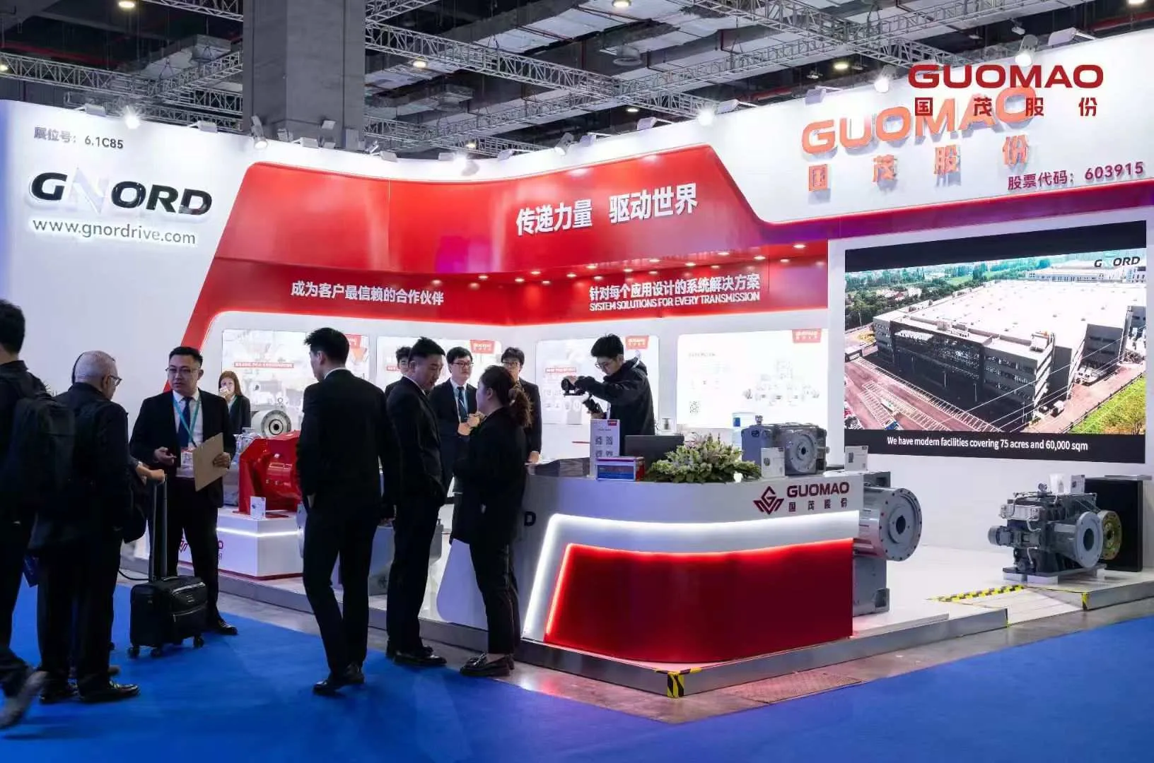
Guomao specifies grade 6 tooth accuracy with profile modification for its H Series Industrial Gearbox. Its source also identifies carburized-steel forgings, controlled heat treatment, gear grinding, fatigue testing, and capacity calculations to relevant GB, DIN, and ISO standards. These features support accurate contact and industrial load carrying without making shaft layout the primary claim.
Bearing Selection and Expected Life Under Continuous Load
Bearing selection must include mesh reactions, external loads, speed, lubrication, contamination, and housing stiffness. The H Series source provides conditional bearing-life statements tied to specific service factors; those figures are product conditions, not universal recommendations. Our engineers should verify the complete load case before assigning expected life.
Housing Rigidity, Alignment, and Assembly Accuracy
A rigid housing and foundation preserve alignment as torque and temperature change. Coupling coaxiality, base flatness, shaft-load location, and clean assembly prevent concentrated tooth and bearing loads.
Lubrication and Sealing for Extended Operating Hours
Lubrication must suit speed, mounting, ambient conditions, and heat load. Seals control leakage and contamination; oil level, filters, breathers, lines, and coolers require inspection access.
How Does Industrial Gear Reducer Performance Vary Across Continuous-Duty Applications?
Sustained Torque Performance in Mixers and Process Equipment
Mixers can combine long running periods with changing material viscosity and startup torque. The reducer needs continuous torque and thermal margin plus a shaft arrangement suited to process loads. Trend motor load through real batches rather than relying on a single design value.
Continuous and Peak Load Performance in Crushers and Material Handling
Conveyors apply sustained torque, while crushers and transfer points can add impact or jams. Record normal, startup, peak, and exceptional loads separately. Overload protection should prevent a process event from becoming repeated tooth or bearing damage.
Variable-Load Performance in Hoisting and Port Equipment
Hoisting and port drives add acceleration, braking, reversals, and variable suspended loads. Selection must address peak torque, starts per hour, load holding, external forces, and the applicable safety requirements, while thermal assessment uses the full operating cycle.
How Does Drive Arrangement Influence Performance Under Continuous Duty?
Direction changes, shaft orientation, and installation space determine the practical arrangement. Our B Series Industrial Gearbox supports applications that require a change in transmission direction and industrial load capacity. Final selection still depends on torque, loads, mounting, lubrication, and cooling.
How Can Engineers Verify Industrial Gear Reducer Performance in Service?
Confirm Stable Torque, Output Speed, and Motor Load
Establish a baseline after alignment and staged loading. Compare motor current, speed, output, and measured torque with the design spectrum, and investigate drift.
Track Oil and Bearing Temperature After Thermal Equilibrium
Record temperature from startup until it stabilizes, using consistent sensor locations and ambient conditions. Thermal inertia means a short reading cannot prove equilibrium. Compare trends with manufacturer limits for the exact lubricant, bearings, and gearbox configuration.
Monitor Vibration, Noise, and Lubricant Condition
Trend vibration and noise with load and speed, and inspect oil level, leakage, particles, water, viscosity, filters, and circulation pressure where applicable. A change across several indicators is more informative than one isolated measurement.
Identify Performance Drift Before Gear or Bearing Damage Develops
Rising temperature, motor load, vibration, debris, or leakage should trigger checks of load, alignment, foundation, gears, bearings, seals, and cooling. Early comparison with a clean baseline helps separate process changes from mechanical deterioration.
FAQ
Q: How long can an industrial gear reducer run continuously?
A: It can run continuously only when the selected model satisfies mechanical and thermal ratings at the real duty, ambient conditions, lubrication, and cooling arrangement. A 24/7 schedule is not itself a product rating.
Q: What service factor is needed for an industrial gear reducer in continuous-duty equipment?
A: Determine it from load severity, hours, starts, stops, reversals, inertia, ambient conditions, and reliability requirements, then apply the selected manufacturer’s method. There is no responsible universal value.
Q: How efficient is an industrial gear reducer during continuous operation?
A: Efficiency depends on gear stages, geometry, speed, load, bearings, seals, oil viscosity, and churning. Use verified manufacturer data at the intended operating point and include resulting losses in the thermal assessment.
Q: What causes an industrial gear reducer to overheat during continuous operation?
A: Common causes include overload, excessive losses, wrong lubricant or oil level, restricted airflow, failed cooling, bearing or seal friction, misalignment, and high ambient temperature. Diagnose the heat source before adding cooling.