


Выбор редуктора с косозубыми шестернями требует большего, чем просто соответствие мощности двигателя модели из каталога. Устройство должно соответствовать компоновке вала. Оно должно учитывать выходную скорость, крутящий момент, рабочий цикл, положение при монтаже, нагрузки на вал и условия эксплуатации. Все эти элементы работают вместе как единый, взаимосвязанный путь передачи нагрузки.
Что такое коническая зубчатая передача с косозубыми шестернями, и подходит ли она для вашего применения?
Как взаимодействуют косозубые и конические зубчатые передачи?
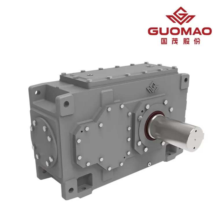
В редукторе с косозубыми шестернями сочетаются косозубые редукторы и конические шестерни. Постепенное зацепление косозубых зубьев обеспечивает равномерную передачу крутящего момента. Конические шестерни перераспределяют мощность. Это позволяет входному и выходному валам работать под углом примерно 90 градусов.
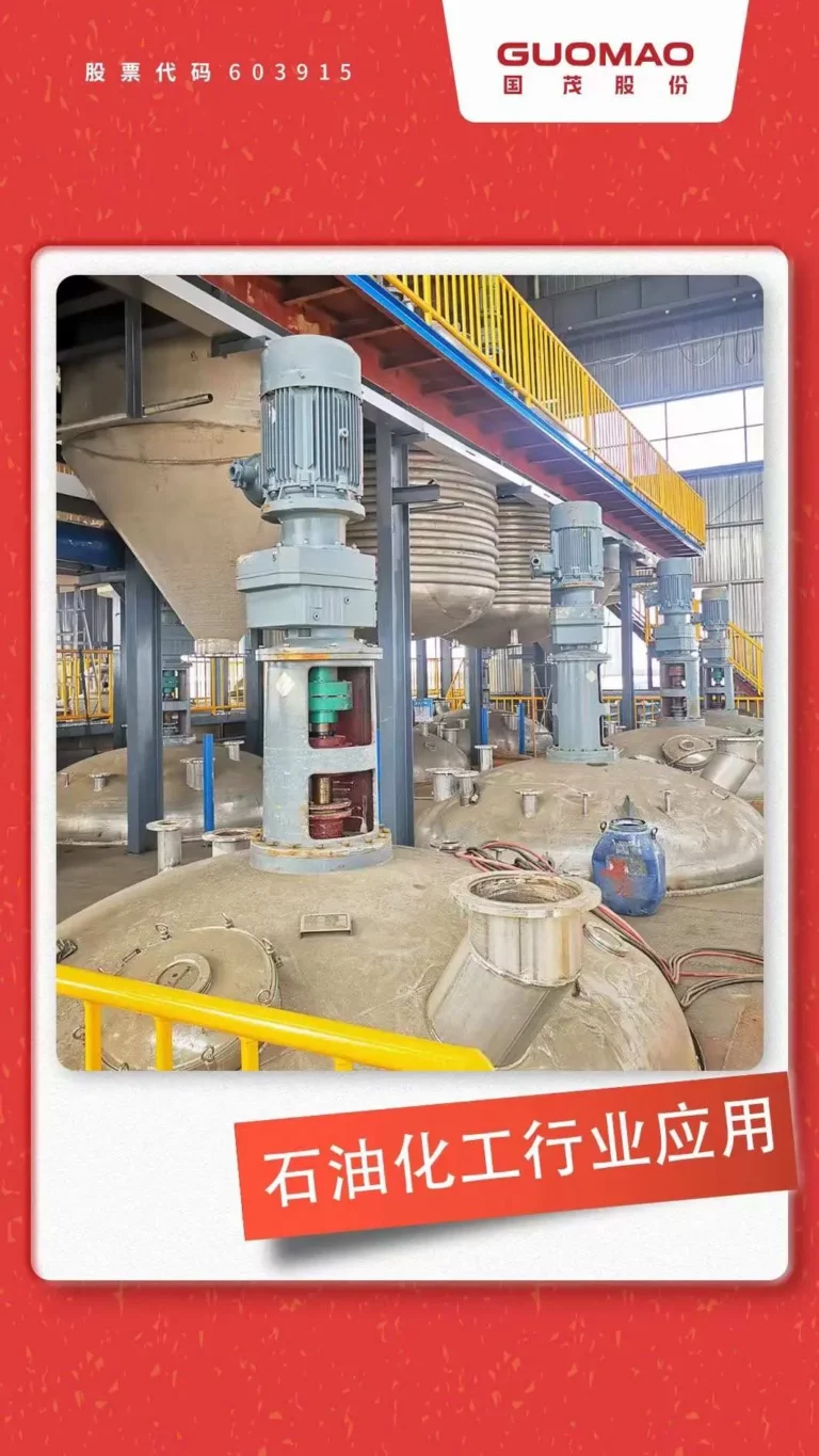
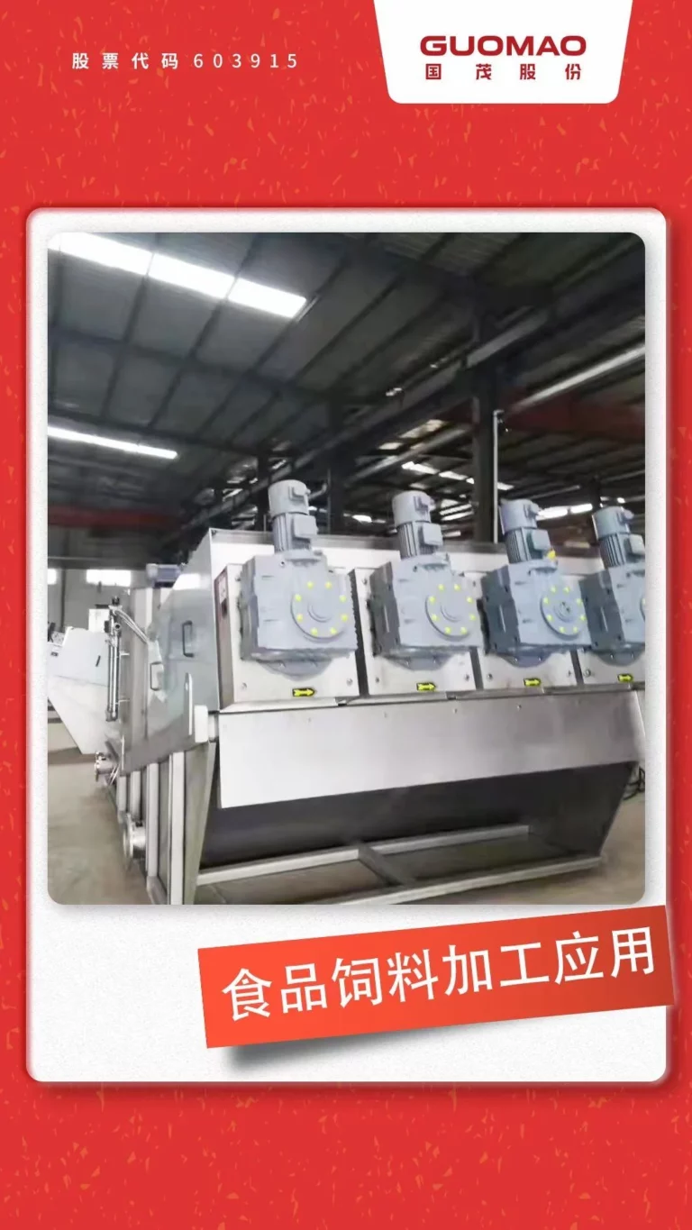
Это делает его полезным угловым редуктором в тех случаях, когда двигатель не может быть выровнен с ведомым валом. К таким случаям относятся конвейеры, подъемные механизмы, смесители и технологическое оборудование. Зачастую для них требуется компактная передача мощности под углом 90 градусов.
Подходит ли конический редуктор с косозубыми шестернями для вашей схемы привода промышленного оборудования?
Начнём с геометрии. Косозубый конический редуктор для промышленного оборудования идеально подходит, когда необходимы перпендикулярные валы, эффективная непрерывная передача и стабильная передача крутящего момента.
Червячный редуктор может удовлетворять специфическим требованиям самоблокировки или обеспечивать высокое одноступенчатое передаточное отношение. Коробка передач с косозубыми шестернями подходит для соосных валов. Сравнивайте их только для того, чтобы убедиться в целесообразности угловой компоновки.
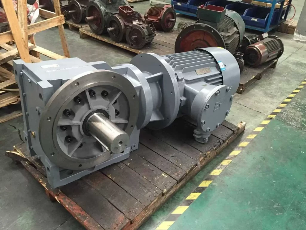
Для модульных угловых приводов... GK серия спирального мотор с шерстями Используется два косозубых и один конический редуктор. Его перпендикулярные входной и выходной валы полностью соответствуют механическим характеристикам косозубого конического редуктора.
Какие эксплуатационные данные необходимы для выбора конической зубчатой передачи?
Определите мощность двигателя, входную скорость и требуемую выходную скорость.
Запишите номинальную мощность двигателя. Отметьте его фактическую скорость при полной нагрузке. Запишите требуемую скорость вращения машины, способ пуска, направление вращения и полный диапазон скоростей частотно-регулируемого привода. Для точного расчета мощности двигателя с коническим редуктором следует использовать фактическую рабочую скорость. Не следует использовать только синхронную скорость двигателя.
Низкие скорости вращения частотного преобразователя могут ухудшить охлаждение двигателя. Высокие скорости могут превысить предельные значения входного напряжения редуктора. По этим причинам необходимо проверить весь рабочий диапазон.
Зафиксируйте фактический профиль нагрузки и рабочий цикл.
Тип приводимого механизма определяет режим работы. Запишите тип нагрузки. Отметьте часы работы, количество пусков в час, время разгона, временные перегрузки, условия блокировки и момент отрыва.
| Выбор ввода | Что нужно проверить | Почему это важно |
| Постоянная нагрузка | Нормальный крутящий момент и количество часов работы в сутки | Определяет непрерывную мощность |
| Начало загрузки | Крутящий момент при трогании и ускорении | Контролирует кратковременный спрос |
| Изменение нагрузки | Шок, реверсия или блокировка | Влияет на коэффициент обслуживания и пиковую мощность. |
Конвейер, начинающий работу с грузом, и конвейер, начинающий работу с пустым грузом, могут использовать один и тот же двигатель. Однако они предъявляют разные требования к рабочим циклам промышленных редукторов. Как только профиль известен, мы в Гумао Разделите крутящий момент при движении и кратковременные пики. Такой подход позволяет избежать сокрытия обоих параметров в рамках одной общей области.
Выявление экологических и монтажных ограничений
Необходимо убедиться в наличии следующих факторов: температура окружающей среды, пыль, влажность, коррозия, вентиляция, пространство для установки и доступ для технического обслуживания. Эти условия влияют на герметичность, вязкость смазки и теплоотвод.
Положение крепления коробки передач также должно обеспечивать правильное распределение масла. Оно должно обеспечивать доступ к сапуну, сливному отверстию и точке измерения уровня масла. Правильный расчет момента затяжки не может компенсировать недостаточную смазку. Недостаточная смазка часто возникает из-за неправильной ориентации.
Как правильно подобрать передаточное число, крутящий момент и коэффициент запаса прочности для конической зубчатой передачи?
Рассчитайте требуемое передаточное число редуктора и скорость вращения выходного вала.
Использовать:
Требуемое передаточное число = скорость вращения входного вала ÷ требуемая скорость вращения выходного вала
Для двигателя со скоростью вращения 1470 об/мин, приводящего в движение машину со скоростью 49 об/мин, требуется передаточное отношение приблизительно 30:1. Представленные в каталоге передаточные отношения являются дискретными. Выберите ближайшее подходящее передаточное отношение. Затем пересчитайте фактическую выходную скорость.
Полный расчет передаточного отношения конического редуктора с косозубыми шестернями также включает проверку максимальной входной скорости, проверку предельных значений частотно-регулируемого привода и анализ допустимого отклонения выходной скорости процесса.
Рассчитайте требуемый выходной крутящий момент конической зубчатой передачи.
Крутящий момент непрерывной работы
Используйте необходимую мощность на ведомом валу:
Выходной крутящий момент (Н·м) = 9550 × выходная мощность (кВт) ÷ скорость вращения выходного вала (об/мин)
При начале расчета мощности двигателя используйте проверенный запас КПД. Не предполагайте передачу без потерь. Полученный результат определяет требуемый непрерывный выходной крутящий момент.
Начальный, пиковый и ударный крутящий момент
Проверьте пусковой момент. Отдельно изучите сопротивление отрыву, ускорение при высокой инерции, заклинивания и скачки нагрузки. Редуктор должен соответствовать как номинальной мощности в непрерывном режиме, так и допустимой пиковой мощности в кратковременном режиме. Одной лишь мощности двигателя может быть недостаточно для защиты шестерен, валов или подшипников.
Преобразуйте профиль нагрузки в правильный коэффициент запаса прочности редуктора.
А коробка передач При расчете коэффициента запаса прочности следует учитывать количество часов работы, число запусков в час, колебания нагрузки, частоту реверсирования, интенсивность ударных нагрузок и требуемую надежность.
Коэффициент запаса прочности корректирует номинальную мощность в зависимости от интенсивности эксплуатации. Он не заменяет проверки пикового крутящего момента, радиальной нагрузки, теплоемкости или смазки. Это различие предотвращает как небезопасный заниженный, так и ненужный завышенный расчет размеров.
Какая конфигурация крепления и вала конической зубчатой передачи подходит для вашей машины?
Выберите между цельным и полым выходным валом.
Коробка передач с косозубыми шестернями и цельным валом подходит для муфт, звездочек, зубчатых колес и шкивов. Консольные компоненты могут создавать значительную радиальную нагрузку.
Коробка передач с конической зубчатой передачей и полым валом, оснащенная стопорным диском, может быть установлена непосредственно на ведомый вал. Это уменьшает количество внешних соединительных элементов. Перед установкой необходимо спланировать посадку на вал, плечо крутящего момента, осевое крепление и способ демонтажа.
В серии Guomao GK предлагаются варианты с цельными выходными валами и полыми выходными валами с блокировочными дисками. Эти варианты позволяют адаптировать интерфейс редуктора к компоновке машины.
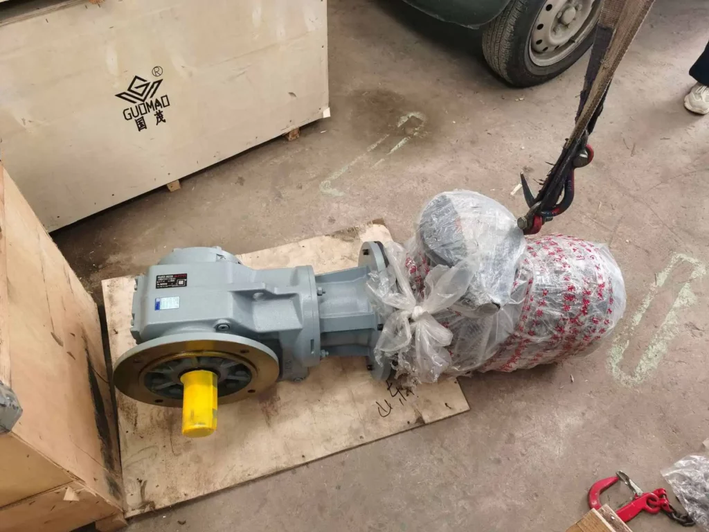
Выберите способ монтажа и положение установки.
Доступные варианты крепления включают опору, фланец B5, фланец B14, вал и рычаг крутящего момента. Выбор варианта влияет на опору, реактивные силы, соосность, смазку и доступ.
Эти конфигурации GK особенно полезны в системах с косозубыми коническими редукторами, установленными на валу. В таких системах направление рычага крутящего момента должно соответствовать фактической реактивной нагрузке. Оно не должно совпадать с наиболее удобным расположением кронштейна.
Проверьте нагрузку на вал, соосность и совместимость соединений.
Проверьте радиальную нагрузку, создаваемую шкивами, звездочками или шестернями. Отметьте ее направление и расстояние от упора вала. Также проверьте осевую нагрузку, соосность муфты, посадку полого вала, размеры фланца двигателя, диаметр вала, стопорное соединение и направление вращения.
Правильные значения крутящего момента и мощности не защищают подшипники от неправильной центровки или чрезмерной консольной нагрузки.
Как проверить окончательный выбор конической зубчатой передачи перед заказом?
Проверьте механические характеристики, теплоемкость и совместимость со смазочными материалами.
Проверьте постоянный крутящий момент, пиковый крутящий момент, коэффициент запаса прочности, максимальную входную скорость, радиальные и осевые нагрузки, температуру окружающей среды, теплоемкость, герметичность и смазку. Сравните схему смазки с точным местом установки. Не полагайтесь на типовое изображение изделия.
Сопоставьте расчетные требования с конфигурацией Guomao GK Series.
Примените расчет к полной конфигурации. Не ограничивайтесь только типоразмером. Наши редукторные двигатели Guomao серии GK с косозубыми шестернями выпускаются с номинальной мощностью от 0,12 до 200 кВт, передаточными числами от 1,26 до 33 000 и максимальным крутящим моментом до 50 кН·м.
В компании Guomao мы объединяем передаточное число, крутящий момент, коэффициент запаса прочности, способ крепления, конструкцию вала, интерфейс двигателя и рабочее положение в единую спецификацию. Эта серия предназначена для конвейерного, подъемного и технологического оборудования, работающего на новых источниках энергии. Для таких применений необходимы модульные угловые трансмиссии, низкий уровень шума и возможность работы с радиальными нагрузками. К соответствующим областям применения относятся системы зарядки, гомогенизирующее оборудование, системы транспортировки суспензий, системы клеевых машин, ленточные конвейеры, винтовые конвейеры и лебедки.
Какую информацию следует включить в окончательную спецификацию коробки передач?
В техническом запросе должно быть указано:
- Применение и приводное оборудование
- Мощность двигателя и фактическая входная скорость
- Требуемая скорость и передаточное отношение на выходе
- Постоянный, пусковой и пиковый крутящий момент
- Коэффициент обслуживания, часы работы и количество запусков в час.
- Положение крепления и тип выходного вала
- Радиальные и осевые нагрузки
- интерфейс двигателя
- Требования к условиям окружающей среды, герметизации и смазке.
Этот контрольный список для выбора промышленных редукторов позволяет избежать неопределенности в работе инженерных групп, отделов закупок и поставщиков.
Избегайте распространенных ошибок при выборе косозубых конических редукторов.
Избегайте выбора, ориентируясь только на мощность двигателя. Не игнорируйте пиковый крутящий момент. Не допускайте ошибки при пересчете выходной скорости. Не упускайте из виду консольную нагрузку. Избегайте выбора неправильного положения при монтаже. Не предполагайте самоблокировку. Не пренебрегайте ориентацией сапуна и системы смазки.
Часто задаваемые вопросы
В: Как рассчитать передаточное число для конической зубчатой передачи?
A: Разделите фактическую скорость вращения двигателя на требуемую выходную скорость. Выберите ближайшее доступное передаточное отношение. Затем пересчитайте выходную скорость, чтобы убедиться, что машина может выдержать разницу.
В: Как правильно подобрать размер редуктора с косозубыми шестернями для обеспечения необходимого крутящего момента на выходе?
А: Рассчитайте непрерывный крутящий момент, исходя из выходной мощности и скорости. Затем отдельно проверьте пусковой, ударный и пиковый крутящий момент. После выполнения этих шагов примените соответствующий коэффициент запаса прочности.
В: Подходит ли конический редуктор с косозубыми шестернями для работы в условиях непрерывной эксплуатации?
А: Да. Механические характеристики, теплоемкость, смазка, коэффициент запаса прочности, входная скорость и условия окружающей среды должны быть проверены в реальных условиях эксплуатации.
В: Какой редуктор с косозубыми шестернями выбрать — с цельным или полым валом?
А: Для наружных муфт или шкивов используйте цельный вал. Для прямого крепления вала используйте полый вал. В обоих случаях проверьте посадку, радиальную нагрузку, конструкцию рычага крутящего момента и доступ для снятия.
В: Какая информация необходима для заказа редуктора с косозубыми шестернями?
A: Укажите область применения, характеристики двигателя, входную и выходную скорости, непрерывный и пиковый крутящий момент, рабочий цикл, способ монтажа, тип вала, внешние нагрузки, условия окружающей среды и требования к смазке.