


La elección de una caja de engranajes cónicos helicoidales requiere más que simplemente hacer coincidir la potencia del motor con un modelo de catálogo. La unidad debe ser compatible con la configuración del eje, la velocidad de salida, el par, el ciclo de trabajo, la posición de montaje, las cargas del eje y el entorno. Todos estos elementos funcionan conjuntamente como una única trayectoria de carga conectada.
¿Qué es una caja de engranajes cónicos helicoidales y es la adecuada para su aplicación?
¿Cómo funcionan conjuntamente las etapas de engranajes helicoidales y cónicos?
Una caja de engranajes cónicos helicoidales combina etapas de reducción helicoidal con una etapa de engranajes cónicos. El acoplamiento gradual de los dientes helicoidales garantiza una transmisión uniforme del par. La etapa cónica redirige la potencia, lo que permite que los ejes de entrada y salida operen a unos 90 grados.
Esto la convierte en una útil caja de engranajes de ángulo recto donde el motor no puede alinearse con el eje accionado. Algunos ejemplos son las cintas transportadoras, los mecanismos de elevación, las mezcladoras y los equipos de proceso, que a menudo requieren una transmisión de potencia compacta de 90 grados.
¿Es una caja de engranajes cónicos helicoidales adecuada para su sistema de transmisión industrial?
Comencemos con la geometría. Una caja de engranajes cónicos helicoidales para maquinaria industrial es la opción ideal cuando se requieren ejes perpendiculares, una transmisión continua eficiente y una entrega de par estable.
Una caja de engranajes de tornillo sin fin puede ser adecuada para necesidades específicas de autobloqueo o alta reducción en una sola etapa. Una caja de engranajes helicoidales en línea es apropiada para ejes coaxiales. Compárelas solo para confirmar que una disposición en ángulo recto está justificada.
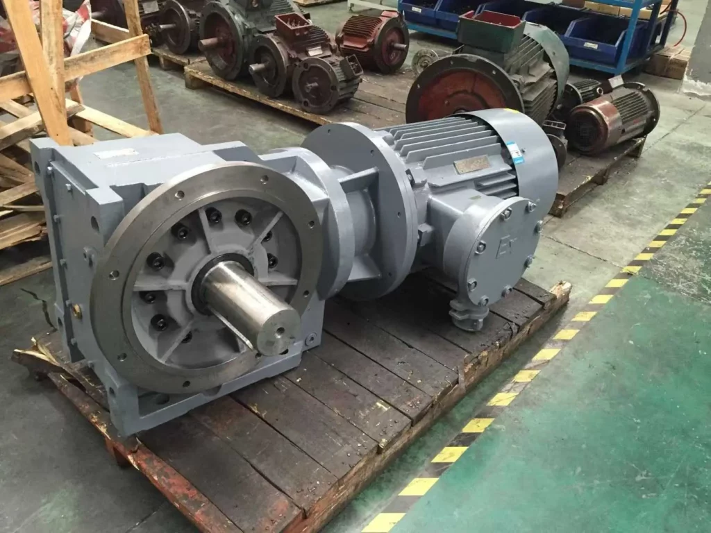
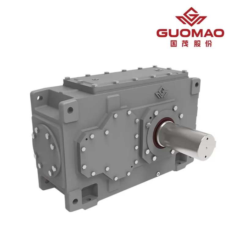
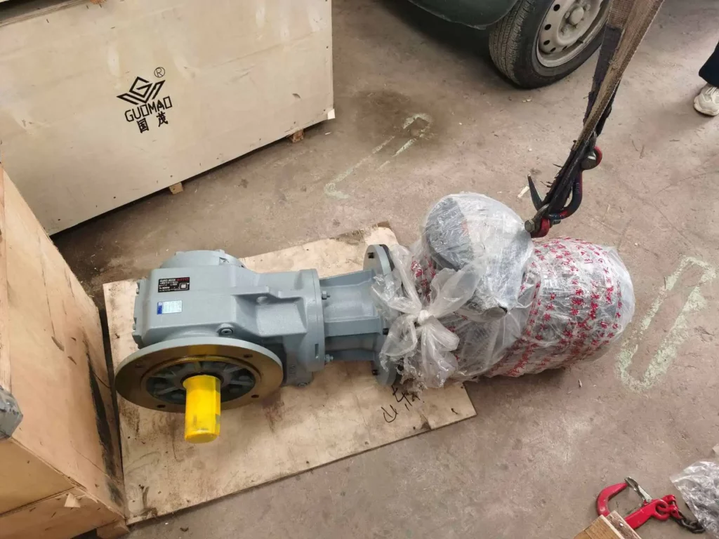
Para accionamientos de ángulo recto modulares, el Serie GK Motor con engranaje helicoidal Utiliza dos etapas helicoidales y una etapa cónica. Sus ejes de entrada y salida perpendiculares se ajustan completamente a la definición mecánica de una caja de engranajes cónicos helicoidales.
¿Qué datos operativos se requieren para la selección de una caja de engranajes cónicos helicoidales?
Defina la potencia del motor, la velocidad de entrada y la velocidad de salida requerida.
Registre la potencia nominal del motor. Anote su velocidad real a plena carga. Registre la velocidad requerida de la máquina, el método de arranque, el sentido de giro y el rango completo de velocidad del variador de frecuencia. Para dimensionar correctamente un motor con reductor de engranajes cónicos helicoidales, debe utilizarse la velocidad de funcionamiento real, no solo la velocidad síncrona.
Las bajas velocidades del variador de frecuencia pueden reducir la refrigeración del motor. Las altas velocidades pueden exceder el límite de entrada de la caja de engranajes. Por estos motivos, verifique el rango de funcionamiento completo.
Registrar el perfil de carga real y el ciclo de funcionamiento.
La máquina accionada determina el servicio. Registre el tipo de carga. Anote las horas de funcionamiento, los arranques por hora, el tiempo de aceleración, las sobrecargas temporales, las condiciones de bloqueo y el par de arranque.
| Entrada de selección | Qué verificar | Por qué es importante |
| Carga en ejecución | Par normal y horas de funcionamiento por día | Define la capacidad continua |
| Inicio de carga | Par de arranque y aceleración | Controla la demanda de corta duración |
| Variación de carga | Choque, inversión o bloqueo | Afecta al factor de servicio y a la calificación máxima. |
Una cinta transportadora que comienza cargada y otra que comienza vacía pueden usar el mismo motor. Sin embargo, imponen diferentes ciclos de trabajo a la caja de engranajes industrial. Una vez que se conoce el perfil, nosotros en Guomao Separar el par motor en funcionamiento de los picos de corta duración. Este enfoque evita que ambos se confundan dentro de un mismo margen.
Identificar las limitaciones ambientales y de instalación.
Verifique la temperatura ambiente, la presencia de polvo, humedad, corrosión, ventilación, espacio de instalación y acceso para mantenimiento. Estas condiciones afectan el sellado, la viscosidad del lubricante y la disipación de calor.
La posición de montaje de la caja de cambios también debe garantizar una correcta distribución del aceite. Debe permitir el acceso a los puntos de ventilación, drenaje y nivel de aceite. Un cálculo de par válido no puede compensar una lubricación deficiente. Una lubricación deficiente suele deberse a una orientación incorrecta.
¿Cómo se dimensiona una caja de engranajes cónicos helicoidales en función de la relación de transmisión, el par motor y el factor de servicio?
Calcular la relación de reducción de engranajes y la velocidad de salida requeridas.
Usar:
Relación de transmisión requerida = velocidad de entrada ÷ velocidad de salida requerida
Un motor de 1470 rpm que acciona una máquina a 49 rpm requiere una relación de aproximadamente 30:1. Las relaciones del catálogo son discretas. Seleccione la relación adecuada más cercana. A continuación, recalcule la velocidad de salida real.
El cálculo completo de la relación de transmisión de la caja de engranajes cónicos helicoidales también verifica la velocidad máxima de entrada. Revisa los límites del variador de frecuencia (VFD). Examina la tolerancia de velocidad de salida aceptable del proceso.
Calcular el par de salida requerido para la caja de engranajes cónicos helicoidales.
Par de funcionamiento continuo
Utilice la potencia requerida en el eje accionado:
Par de salida (N·m) = 9550 × potencia de salida (kW) ÷ velocidad de salida (rpm)
Cuando el cálculo comience con la potencia del motor, utilice un margen de eficiencia verificado. No asuma una transmisión sin pérdidas. Este resultado define el par de salida continuo requerido.
Par de arranque, par máximo y par de impacto
Compruebe el par de arranque. Analice por separado la resistencia al arranque, la aceleración por alta inercia, los atascos y las sobretensiones. La caja de engranajes debe cumplir tanto con la potencia nominal continua como con la potencia nominal máxima admisible de corta duración. La potencia del motor por sí sola puede no proteger los engranajes, los ejes ni los cojinetes.
Convierta el perfil de carga en el factor de servicio de la caja de cambios correcto.
El caja de cambios El cálculo del factor de servicio debe reflejar las horas de funcionamiento, los arranques por hora, la variación de la carga, la frecuencia de inversión de giro, la gravedad de los choques y la fiabilidad requerida.
El factor de servicio ajusta la capacidad nominal según la severidad de la carga. No sustituye las comprobaciones de par máximo, carga radial, capacidad térmica ni lubricación. Esta distinción evita tanto el sobredimensionamiento peligroso como el sobredimensionamiento innecesario.
¿Qué configuración de montaje y eje de la caja de engranajes cónicos helicoidales se adapta a su máquina?
Elija entre un eje de salida macizo o hueco.
Una caja de engranajes cónicos helicoidales de eje sólido es adecuada para acoplamientos, piñones, engranajes y poleas. Los componentes en voladizo pueden generar una carga radial significativa.
Una caja de engranajes cónicos helicoidales de eje hueco con disco de bloqueo se puede montar directamente en el eje accionado. Esto reduce la cantidad de componentes de acoplamiento externos. Antes de la instalación, es necesario planificar el ajuste del eje, el brazo de torsión, la restricción axial y el método de desmontaje.
La serie Guomao GK ofrece ejes de salida macizos y huecos con discos de bloqueo. Estas opciones permiten que la interfaz de la caja de engranajes se adapte al diseño de la máquina.
Seleccione la disposición de montaje y la posición de instalación.
Las opciones de montaje incluyen pie, brida B5, brida B14, eje y brazo de torsión. La elección influye en el soporte, las fuerzas de reacción, la alineación, la lubricación y el acceso.
Estas configuraciones GK son especialmente útiles en sistemas de engranajes cónicos helicoidales montados sobre eje. En estos sistemas, la dirección del brazo de torsión debe coincidir con la carga de reacción real. No debe seguir la ubicación más conveniente del soporte.
Compruebe las cargas del eje, la alineación y la compatibilidad de la interfaz.
Compruebe la carga radial producida por poleas, piñones o engranajes. Anote su dirección y distancia desde el hombro del eje. Verifique también la carga axial, la alineación del acoplamiento, el ajuste del eje hueco, las dimensiones de la brida del motor, el diámetro del eje, la conexión de bloqueo y el sentido de giro.
Los valores correctos de par y potencia no protegen los cojinetes de una mala alineación o de una carga excesiva en voladizo.
¿Cómo se verifica la selección final de la caja de engranajes cónicos helicoidales antes de realizar el pedido?
Verifique la clasificación mecánica, la capacidad térmica y la compatibilidad de lubricación.
Confirme el par continuo, el par máximo, el factor de servicio, la velocidad máxima de entrada, las cargas radiales y axiales, la temperatura ambiente, la capacidad térmica, el sellado y la lubricación. Verifique la disposición de la lubricación con respecto a la posición de montaje exacta. No se fíe de una imagen genérica del producto.
Mapear los requisitos calculados a una configuración de la serie Guomao GK
Mapea el cálculo a una configuración completa. No te limites a un solo tamaño de bastidor. Nuestro motorreductor helicoidal-cónico de la serie Guomao GK cubre potencias de 0,12 a 200 kW, relaciones de 1,26 a 33 000 y un par de salida máximo de hasta 50 kN·m.
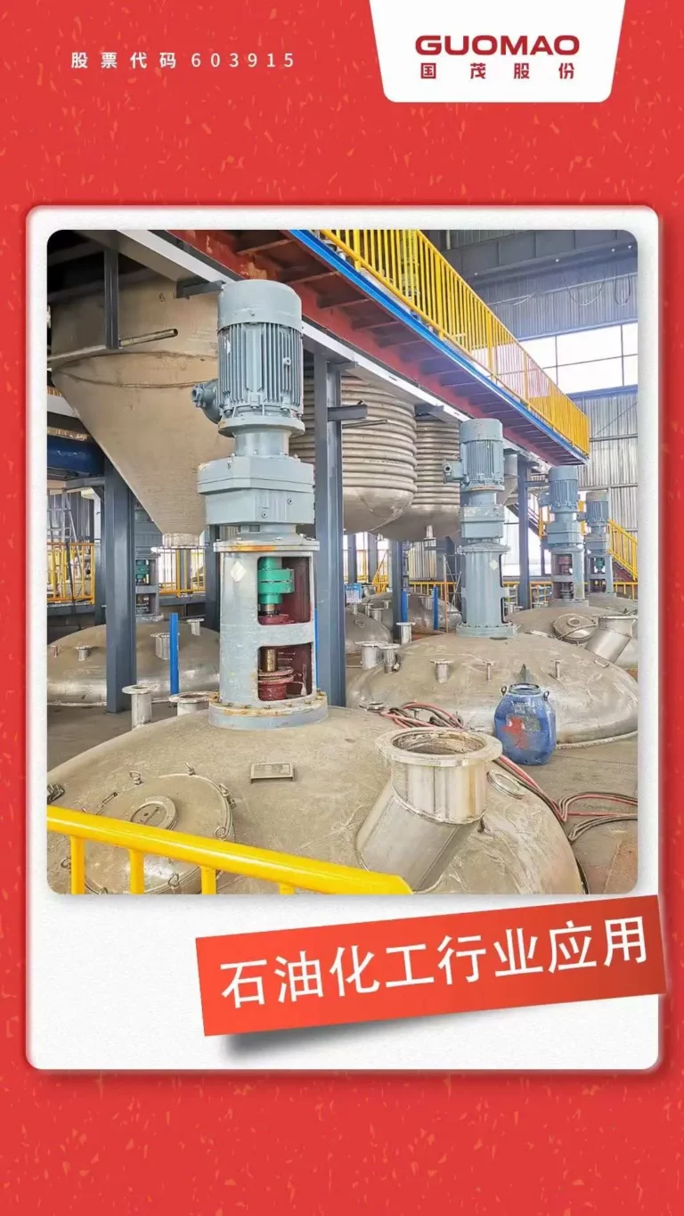
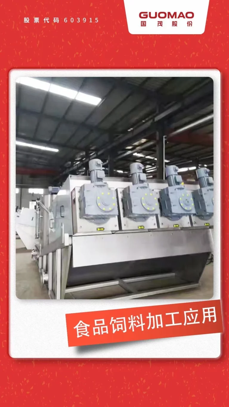
En Guomao, integramos la relación de transmisión, el par motor, el factor de servicio, la disposición de montaje, el diseño del eje, la interfaz del motor y la posición de funcionamiento en una única especificación. Esta serie es compatible con equipos de transporte, elevación y procesos de energías renovables. Estas aplicaciones requieren una transmisión modular en ángulo recto, un funcionamiento silencioso y capacidad de carga radial. Entre las aplicaciones relevantes se incluyen sistemas de carga, equipos de homogeneización, sistemas de transporte de lodos, sistemas de máquinas de encolado, cintas transportadoras, transportadores de tornillo y cabrestantes.
¿Qué información debe incluirse en la especificación final de la caja de cambios?
Una consulta técnica debe indicar:
- Aplicación y equipos accionados
- Potencia del motor y velocidad de entrada real
- Velocidad de salida y relación requeridas
- Par continuo, de arranque y máximo
- Factor de servicio, horas de funcionamiento y arranques por hora
- Posición de montaje y tipo de eje de salida
- Cargas radiales y axiales
- Interfaz del motor
- Requisitos ambientales, de sellado y de lubricación
Esta lista de verificación para la selección de cajas de engranajes industriales reduce la ambigüedad entre los equipos de ingeniería, los departamentos de compras y el proveedor.
Evite los errores comunes al seleccionar reductores de engranajes cónicos helicoidales.
Evite seleccionar únicamente por la potencia del motor. No ignore el par máximo. Evite no recalcular la velocidad de salida. No pase por alto la carga en voladizo. Evite elegir una posición de montaje incorrecta. No dé por sentado que el sistema es autoblocante. Evite descuidar la orientación del respiradero y la lubricación.
Preguntas frecuentes
P: ¿Cómo calculo la relación de transmisión para una caja de engranajes cónicos helicoidales?
A: Divide la velocidad real del motor entre la velocidad de salida requerida. Selecciona la relación más cercana disponible. Luego, recalcula la velocidad de salida para confirmar que la máquina puede tolerar la diferencia.
P: ¿Cómo dimensiono una caja de engranajes cónicos helicoidales para obtener el par de salida deseado?
A: Calcule el par continuo a partir de la potencia de salida y la velocidad. Luego, verifique por separado el par de arranque, el par de impacto y el par máximo. Aplique el factor de servicio correcto después de estos pasos.
P: ¿Es una caja de engranajes cónicos helicoidales adecuada para aplicaciones de servicio continuo?
R: Sí. La clasificación mecánica, la capacidad térmica, la lubricación, el factor de servicio, la velocidad de entrada y las condiciones ambientales deben verificarse en el punto de funcionamiento real.
P: ¿Debo elegir una caja de engranajes cónicos helicoidales de eje macizo o hueco?
A: Utilice un eje macizo para acoplamientos o poleas externas. Utilice un eje hueco para el montaje directo del eje. En ambos casos, compruebe el ajuste, la carga radial, el diseño del brazo de torsión y el acceso para la extracción.
P: ¿Qué información se necesita para pedir una caja de engranajes cónicos helicoidales?
A: Proporcione la aplicación, los datos del motor, las velocidades de entrada y salida, el par continuo y máximo, el ciclo de trabajo, la disposición de montaje, el tipo de eje, las cargas externas, las condiciones ambientales y los requisitos de lubricación.