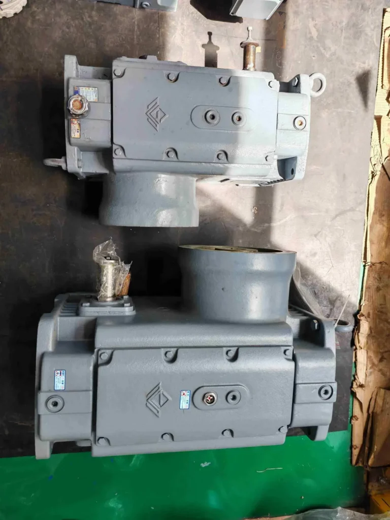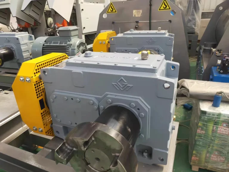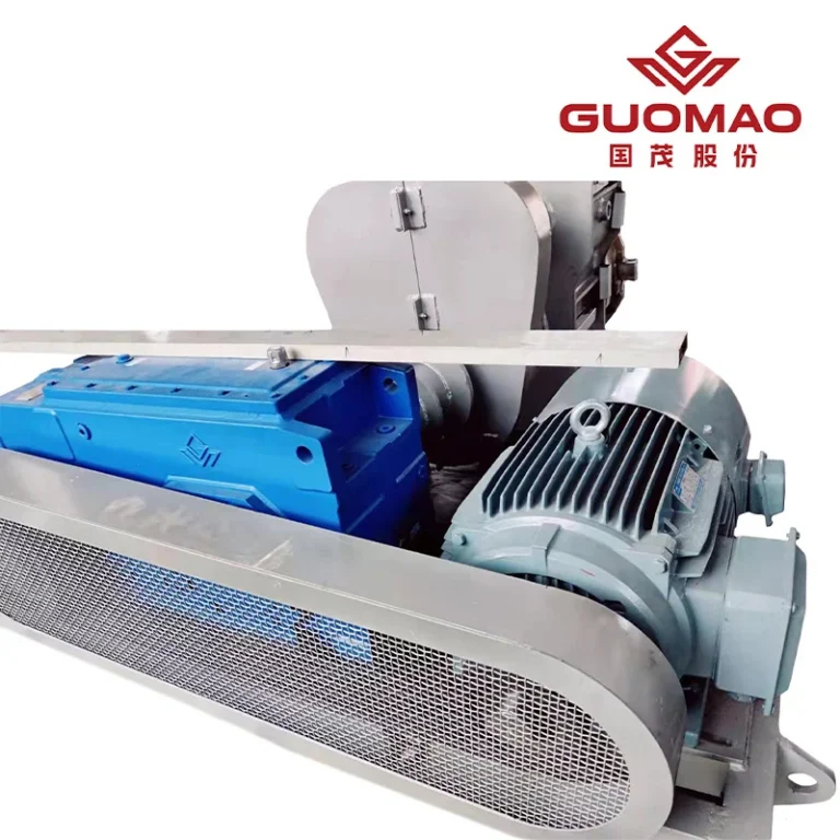



A quotation that shows only motor power leaves the output-shaft duty empty. A loaded transfer conveyor makes start torque part of the choice. A drive that runs without stops makes running hours and heat the main concern. For an industrial gearbox in metallurgical equipment, record the machine it serves and the output speed it must deliver. Enter running torque, short peaks, starts per shift, daily hours, and shaft clearance in the same record. The record shows which duty governs selection.
What Metallurgical Equipment Requires from an Industrial Gearbox
Match gearbox duty to the machine's load pattern
Place start torque next to the roller table's acceleration time. Place running torque in a second field, with hours noted. A transfer drive that seldom stops may be governed by sustained load. Direction changes and material surges belong in the record as events, with their frequency shown. Motor nameplate power and speed do not capture reversal or surge loads. Calculate the ratio from the target speed before checking the required output torque. Locate the peak-torque event on the cycle log before sizing the gearbox.
Account for continuous operation, starts, and load shocks
The duty sheet needs separate fields for event, torque, duration, frequency, and source of measurement. An empty start and a loaded restart need separate entries. A short material surge should carry its observed frequency so its peak is not read as a steady load. Where the plant has no measurement, label the figure as an estimate. The supplier can then show which row controls the calculation. If a quotation omits the governing event, return it for a service-factor and capacity recalculation.
Three inputs govern the working-condition coefficient: load character, hours, and start-stop frequency. Compare quoted factors only after these three entries agree.
How to Select an Industrial Gearbox for Metallurgical Equipment
Define output speed, torque, and operating hours
Use separate fields for the motor and the driven machine on the enquiry. On the motor side, record power and speed. On the machine side, record required output speed, start and running torque, ratio, and daily hours. The speed ratio follows from those speeds. The driven machine sets torque beyond the speed ratio. Mark the centreline of any gear, pulley, or sprocket on the output-shaft drawing. The radial-force check must use that point of application. Keep that force location on the drawing. If a pulley moves toward the shaft tip, repeat the bearing-load check at its new position.
Check service factor against the real load spectrum
Before comparing ratings, read the actual duty assumptions printed on both proposals. Did one include a loaded restart while the other treated running as uninterrupted? Request the normal torque, transient load, and duration used for each service factor. Different assumptions need a recalculation on the shared cycle. With that settled, compare gear and bearing capacity, housing rigidity, material, manufacturing accuracy, and assembly quality for the chosen load.
Attach one start and shock record to the revised enquiry. The industrial gearbox process-duty guide covers related checks.
Gearbox Types and Drive Layouts Used in Metallurgical Lines
Compare helical, bevel, and planetary arrangements by drive needs
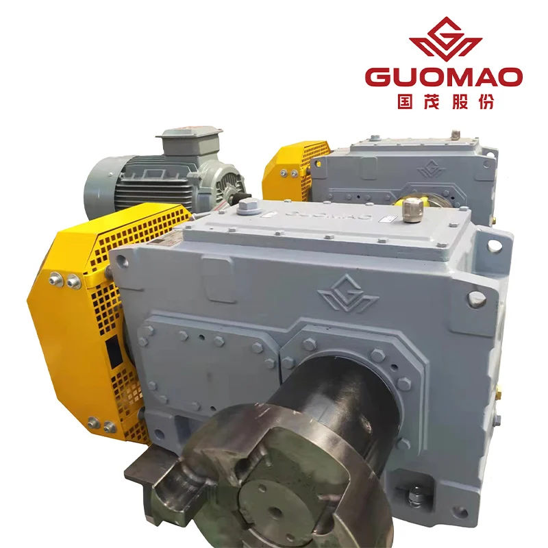
Plot both input and output shaft centre lines against the actual machine interface drawing. A parallel offset or directional turn appears on that overlay before the candidate is rated. A planetary unit might fit a tight envelope, but add its mounting and clearance to the drawing before deciding that the compact form helps.
At Guomao, we offer the HB Series Industrial Gearbox for an application-specific duty review. For HB, grade 6 tooth accuracy applies to the helical and bevel gear pairs; profile modification addresses noise. Circle the quoted HB choices on its drawing: shaft layout, mounting, seals, bearings, housing, and cooling arrangement. Check room for fans, oil circulation, or air coolers at the horizontal or vertical mounting position. The ассортимент промышленных редукторов identifies forms, while the quotation must identify the configuration.
Match mounting and shaft configuration to machine layout
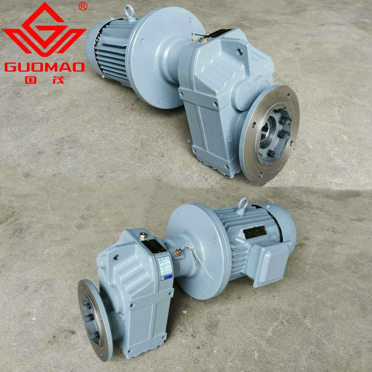
A conveyor beside the machine may call for a different drive type. For a defined auxiliary duty, consider Guomao's Серия GF спиральный шарнир-мотор с параллельным валом, a G Series option. GF transmits through two or three helical stages between parallel shafts. Use the machine interface to choose GF foot, B5 flange, B14 flange, or shaft mounting and a hollow or solid output. Compare its rating only after that interface matches the auxiliary machine.
Locate the drive on the process drawing: is it the heavy-duty machine drive or an auxiliary conveyor? An HB proposal and a GF proposal can then be examined for their respective roles. If one is for the wrong duty, a rating comparison between them has no value.
Managing Heat, Lubrication, and Contamination
Select cooling and oil-circulation options for actual duty
An oil-temperature reading described only as "hot" is difficult to interpret. The selection file needs the duty hours, gearbox location, surrounding air conditions, and intended lubrication method. A fan is useful only if air can pass through the installation; an external oil circuit needs a place to be mounted and maintained. Fans, oil circulation, and air coolers are HB options, not standard on every unit.
The first reading after installation becomes a reference only when load and operating conditions are also recorded. Check the oil level and condition under the chosen unit's instructions. Then examine airflow and load history before deciding what the reading means.
Record the surroundings at that mounting point. Note whether a guard blocks fan airflow or access to oil sampling.
Plan sealing and service access for hot, dusty areas
Choose a seal against conditions at the gearbox, rather than a description of the plant. Mark dust and heat on the drawing. Trace service access to the fill point, drain, seals, and coupling. If blocked, revise the guard or gearbox position before approval.
Compare vibration at matched speed and load; investigate a change. Leakage after shutdown differs from rising bearing temperature during running. Record that context with the date. Start at the coupling, foundation, seals, lubricant, or cooling device as the symptom indicates before inspecting the gears.
Integrating the Gearbox with the Metallurgical Process
Verify interfaces, mounting position, and load path
Align shaft height and coupling geometry; locate the foundation supports and the point where radial force enters the shaft. A sound foundation and suitable coupling coaxiality reduce avoidable vibration. Also mark lubrication access for the mounting position.
Coordinate gearbox selection with the full drive system
Trace its starts, stops, reversals, and upset response. Changing the controls after selection may change the torque history, so the gearbox calculation needs another look. HB and GF can each be considered for their respective roles only with that sequence and the correct shaft interface in hand.
Send bidders a duty table, machine layout, local conditions, and maintenance-access drawing. Ask them to identify the assumption that controls their selection.
Часто задаваемые вопросы
Q: What gearbox information is needed for metallurgical equipment selection?
A: Send the machine drawing and duty log. Output speed and torque need context: hours, loaded starts, peak events, and shaft forces. Label estimates separately from site measurements.
Q: Does a steel mill need the same gearbox for every machine?
A: No. Compare acceleration with hours at running torque. A loaded start may govern one drive; continuous duty another. Check each shaft and mounting interface separately.
Q: How do buyers compare industrial gearboxes for a rolling line?
A: Compare the start sequence and running duty in each proposal. One may allow for a loaded restart; another may not. Reconcile assumptions before comparing ratings.
Q: When is a geared motor suitable instead of an industrial gearbox?
A: For a defined auxiliary conveyor, GF's parallel-shaft layout may fit after mounting, torque, and radial-load checks against the machine drawing and recorded duty. HB belongs to a separate industrial-duty review. A compact housing proves neither choice.
Q: What maintenance conditions matter for metallurgical gearbox reliability?
A: Record load and speed with each reading. For rising vibration, inspect coupling and foundation; for heat, review oil and cooling. Use the installed model's instructions before opening the gearbox.