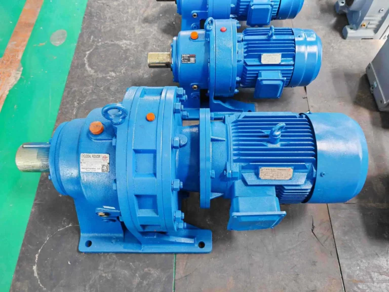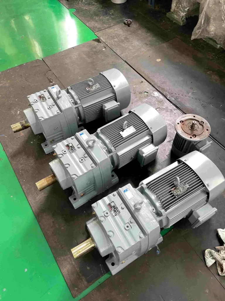



Parallel shaft gearboxes have input and output shafts that are placed in a way that makes compact conveyors, hoists, and winches easier to mount. This advantage has to be checked against mounting, shaft usage, service, and peak torque.
Why Use a Parallel Shaft Gearbox in a Tight Layout?
Measure the complete installed envelope
The gearbox outline is only part of the space requirement. Include the motor, coupling, torque arm, guard, cable bend, lifting route, and removal clearance. Mark both the operating envelope and the maintenance envelope on the machine drawing. A compact assembly can still be impossible to service in a narrow aisle.
Outline the assembly sequence with a sketch for the layout review. Show how the shaft connection is assembled and how the fasteners can be reached. Also show where the reducer will be supported during removal. Note what other equipment will be in the area when the work is done. What is easy to assemble on an open workshop bench may be impossibly located in a completed machine. Check the sketch with the machine designer and with the maintenance people before issuing the final details for mounting the equipment.
Check the operating conditions
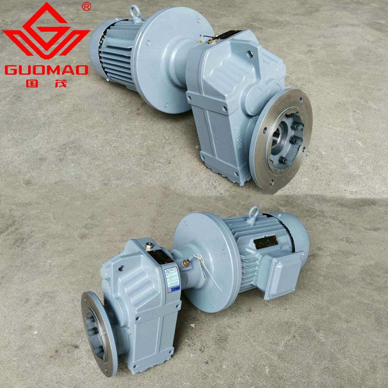
Parallel shafts enable a reduction of the offset between the motor and the driven machine, allowing for flexible foot, flange or shaft mounting. Our Серия GF спиральный шарнир-мотор с параллельным валом consists of two to three helical gear stages and is available with hollow or solid output shafts. The actual selection for the required torque, speed, and time is then made for the respective application.
What Are the Practical Layout Advantages?
Decide between hollow and solid output
A hollow flange output can be mounted directly to a driven shaft, whereas a solid flange output typically requires a separate transmission interface. Compare issues of access, shaft tolerancing, corrosion exposure, and method of removal. Removing a coupling does not necessarily facilitate the installation; the subsequent connection must fit the machine constraints.
Apply the product boundary
GF Series helical gearboxes feature two- to three-gear stages arranged in parallel on straight shafts. Options for mounting include foot, flange, and shaft, as well as hollow or solid shafts. GF gearboxes are compact in modular design and operate quietly. They feature high efficiency and are easily serviced. They can be loaded radially.
How Should External Loads Be Checked?
Draw the applied force on the shaft
Add belt or chain tension to your layout drawing and indicate where the force will act and its direction. A long overhang is important even when the torque being transmitted is small. Check how changing the guarding or the position of a pulley will move this force away from the support of the bearings.
Verify the load inputs
The working-condition coefficient can be influenced by the type of load, working time, and starts/stops of the motor. The power, output speed, output torque, ratio, as well as the radial allowed load are separate selection parameters. The radial load must be checked at the effective point of action of a gear, pulley, or sprocket.
How Does the Gearbox Stay Quiet and Efficient?
Reserve a removal route
Outline the disassembly of the motor and reducer before releasing the layout for production. Identify if adjacent conveyors, structural members, or fixed guardrails block access to the gearbox. Include provision for lifting and support of disconnected components. This review can expose additional costs not shown by a comparison of the purchase price of the gearboxes.
The commissioning log should include the relevant drawing revision number, the installed model of equipment, type of lubricant used, test operating conditions and observer’s comments for each test stage. Unexpected events should be described in detail and action taken recorded. The person authorizing the drive to be released for production after any correction has been implemented should be clearly identified. This person’s responsibility should not get lost when the installation staff hand over to the operators.
Review the installed system
Even progressive helical engagement cannot eliminate noise and loss of efficiency completely. These are a function of tooth accuracy, shaft alignment, lubrication, bearing, housing, and foundation characteristics. The couple should be checked for coaxiality, and the gear and sprocket for parallelism when installed.
How Should Frequent Starts and Reversals Be Managed?
Compare alternative shaft geometries
Parallel shaft, coaxial, and right-angle configurations should be compared on a machine-specific drawing. The best configuration will meet connection, load, access, and operating requirements. A short dimension on a catalog drawing does not necessarily translate to a short overall drive system dimension in use.
Set the monitoring routine
For reducers, lubrication, oil level, cooling, sealing, foundation, alignment, noise, vibration, leakage, and temperature must be checked as described in the reducer documentation and in the installation actually performed.
The items listed below are checked during the inspection of the reducers. The lubricant and lubricant level, as well as the cooling, the seals, the foundation, and the alignment are checked and correspond to the data provided for the respective item, as well as to the installation and to the operating instructions for the selected unit. Noise, vibration, leakage, and temperature are also checked.
Choosing the Right Parallel Shaft Gearbox
Verify the arrangement after installation
Inspect the mounted shaft position, torque lock, connection, and lubrication access against the approved design. Note any deviations from the approved design prior to initiating production. In addition to checking dimensions, an external-load check must be repeated for any chains, pulleys, or driven shafts that have been changed, rather than simply treating these as dimensional changes.
Prepare the engineering handover
For a review of a drive at Гумао, we look at the load case, overall number of operating hours, and start/stop cycles. For the individual values of requested motor power, reduction ratio, output speed, and output torque, we check each value separately; none of them can be replaced by another value. We also check the permitted radial load at the point where the transmission part exerts force.
Часто задаваемые вопросы
Q: How should a parallel shaft gearbox be selected?
A: Start with the actual machine cycle and then verify speed, torque, ratio, shaft loads, mounting, and applicable operating restrictions for the specific model.
Q: What information is needed before installing a parallel shaft gearbox?
A: Provide the interface drawing, applied loads, operating cycle, ambient conditions, lubricant requirements, and access needed for inspection and removal.
Q: Can a parallel shaft gearbox be judged by motor power alone?
A: No. That would require separate checks for output speed, for torque, for reduction ratio, for external load, and for operating cycle.
Q: How should a parallel shaft gearbox be commissioned?
A: Lubricate and install the test equipment. Test at increasing stages of load until normal production running conditions are established and a baseline established for subsequent monitoring.
Q: What should operators monitor on a parallel shaft gearbox?
A: Monitor temperature, vibration, noise, leaks, and oil condition at the same speed and load. Ascertain changes prior to increasing duty.