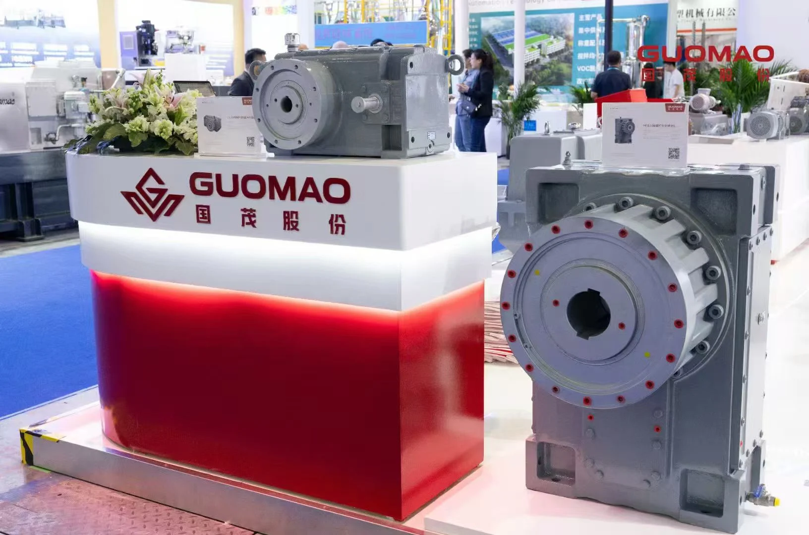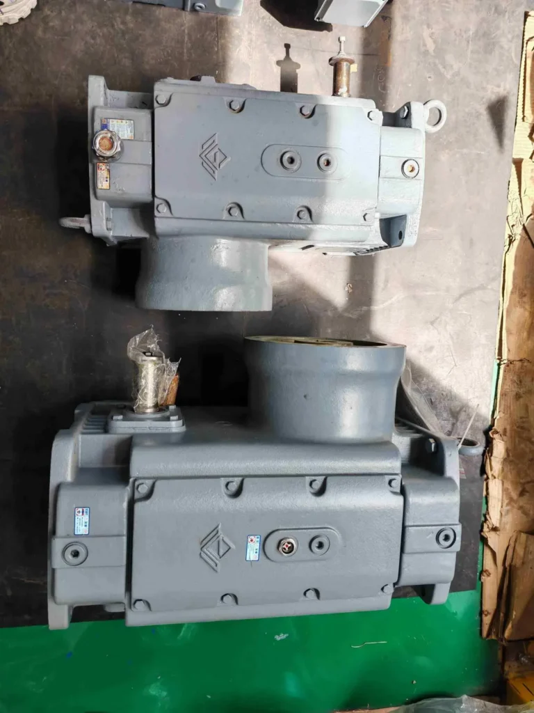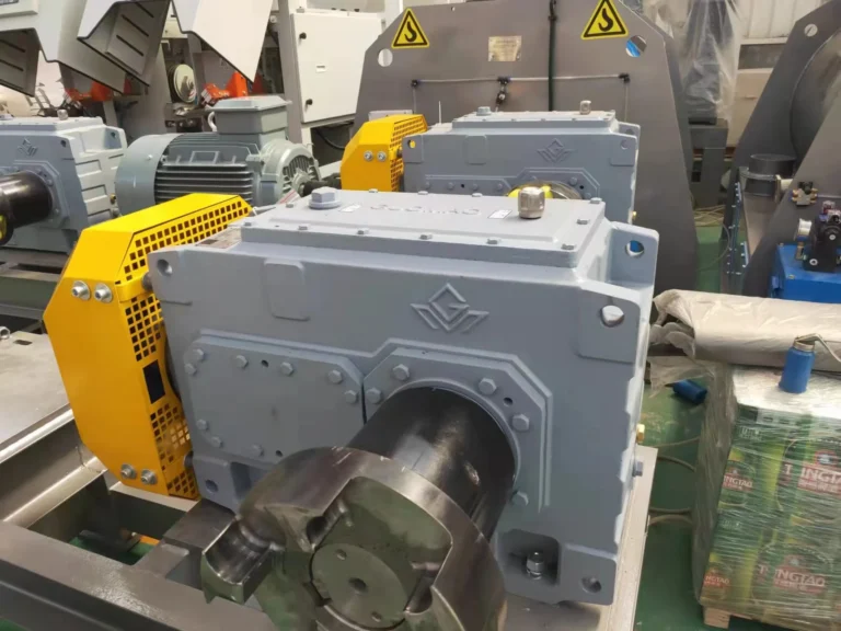



A gearbox mounting arrangement is the mechanical connection by which the housing is attached to its support and the output shaft is connected to the driven machine.
Gearbox Mounting Arrangements
Feet and Bases
Many gear units are mounted on their feet, which are machined on the underside of the casing and are positioned either at the ends of the casing or near the centre, so that the load can be distributed as uniformly as possible over the base. The feet are drilled with holes for holding-down bolts, and the base on which the unit rests must be flat and of adequate strength, usually being of concrete or of steel sections. A hard, smooth surface and accurate alignment of the gear unit are essential. Where possible, the feet should rest evenly on the base without packing-up, although a gear unit may be shimmed as long as the shims cover the full area of the foot and the foot is not strained when the holding-down bolts are tightened.
Flange Connections
Gear units may also be flange-mounted: the output flange on the gear housing is bolted directly to a matching flange on the machine. Flange-mounting is especially suitable for the direct attachment of a geared motor to the driven machine. The driven shaft must be properly aligned with the gear unit to avoid overloading the bearings.
Shaft Geometry and Layout
Right-Angle Drives
Nuestra Serie GK Motor con engranaje helicoidal has perpendicular input and output shafts, two helical stages and one bevel stage. Installation forms include foot-mounted, B5 flange-mounted, B14 flange-mounted, shaft-mounted and torque arm-mounted arrangements. Solid shafts and hollow shafts with locking discs are output options.
The gear unit must be attached to the machine such that its output shaft can be properly aligned with the machine shaft.
Parallel-Shaft Drives
Nuestra Motor helicoidal de eje paralelo de la serie GF has parallel shafts and two or three helical stages. Installation forms include foot-mounted, B5 flange-mounted, B14 flange-mounted and shaft-mounted arrangements.
The shaft-mounted gear unit should be located axially so that it does not interfere with the bearings of the driven machine.
For hollow-shaft gear units the output shaft is usually connected to the driven machine by a keyed or a friction connection.
Multiple input shaft types are available. GF output options include solid shafts and hollow shafts with locking discs.
Loads and Operating Position
External Shaft Loads
Where a gearbox output shaft is not connected directly to the driven machine shaft but carries a belt pulley, a gear wheel, a chain sprocket or similar component, the force at the shaft end must not exceed the maximum overhung load that the gearbox manufacturer specifies for that position.
The permissible overhung load is determined by the strength of the shaft and the load rating of the bearings.
An overhung load applied at the end of a shaft subjects the shaft to bending and the bearing to radial load.
In addition, when a chain or belt drive is used, the loads due to the weight of the chain or belt, the pitch-line force and the initial tension must be taken into account in the calculation of the bearing loads.
The gearbox manufacturer's catalogue should be consulted for the maximum permissible overhung load and for the method of calculating the load at other points along the shaft.
Load characteristics, working time and starts/stops determine the actual working-condition coefficient. Temperature correction and additional safety factors are separate considerations where required. Use the selected product's current manufacturer tables instead of assigning one universal service factor to every installation.
Operating Position
Some designs incorporate an oil pump or a splash lubrication system that operates satisfactorily only in certain positions, and when ordering a gear unit the intended mounting position should be stated.
An oil level plug should be at the correct level for the specified mounting position.
Access and Configuration
Removal Space
While mounting a gearbox, the space around should be considered for future maintenance and inspection.
Reference is also sometimes made to the axial space needed to permit removal of the output shaft or the driven machine spindle from the hollow shaft of the gear unit.
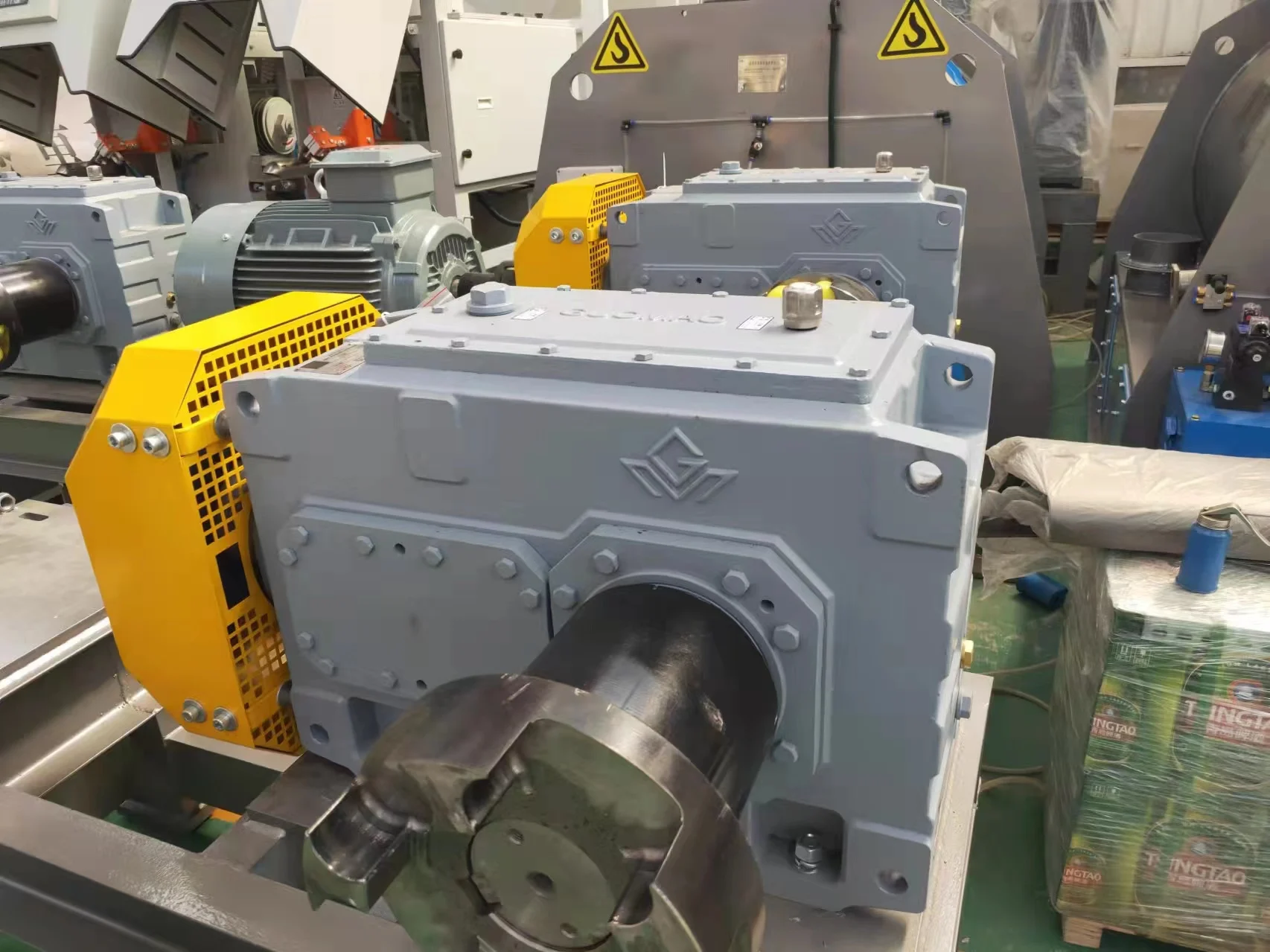
The gear unit should be positioned so that the components of the machine can be easily lubricated and serviced, and the oil level indicator and breather should be accessible for inspection.
Configuration Drawings
In the case of an asymmetric gear unit it is advisable to check the drawing of the gear unit in the order catalogue, so that the mounting position is correctly interpreted before the unit is installed. For example, an oil gauge may have to be visible from a particular side, and the foot position may be on one side only. Installation drawings are of great assistance and should be studied before the gear unit is positioned.
When a gear unit is connected to a machine by a coupling, the two shafts must be accurately aligned. The shafts of the two machines must be within the allowable angular and radial misalignment limits of the coupling. Shaft ends must be square and free from burrs, and the key should fit the keyway properly. The coupling should be fitted without forcing, and the two halves should be separated by the correct gap.
At Guomao, our GK and GF ranges provide the shaft relationships described above. The Categorías de productos de reductores de engranajes identify the product families. The listed mounting forms describe family options; availability of a particular size and combination requires confirmation.
Preguntas frecuentes
Q: What are the main industrial gearbox mounting arrangements?
A: Common arrangements include foot, flange and shaft mounting. They describe different housing or shaft interfaces. Select the form around the machine's support structure, shaft connection and maintenance access, then verify the complete configuration.
Q: Is a flange-mounted gearbox always interchangeable with another unit?
A: No. Compare the locating feature, bolt pattern, flange dimensions, shaft details and operating requirements. Similar appearance or mounting terminology does not establish interchangeability.
Q: Does a right-angle gearbox require vertical installation?
A: No. Right-angle describes the relationship between input and output axes. GK uses perpendicular axes; GF uses parallel axes. Confirm the operating orientation independently.
Q: What should be checked for a shaft-mounted gearbox?
A: Check the driven shaft dimensions, connection, housing restraint, allowable loads and removal procedure. Obtain the configuration drawing before committing the machine interface.
Q: Can gearbox mounting position be changed after delivery?
A: Obtain approval for the new position first. Confirm lubrication, service-point locations, loads and accessory requirements for the revised arrangement before operating the unit.