


Selecting a helical reduction gearbox by motor power alone can hide the most important operating risk: the load does not stay constant throughout a production cycle. A conveyor may run for hours, a mixer may start against a heavy batch, and a lifting mechanism may reverse repeatedly. Each pattern changes torque demand, heat generation, bearing stress, and the margin available for reliable service.
How Duty Cycles Change Helical Reduction Gearbox Performance
Continuous Running and Thermal Load
Continuous duty is governed by the balance between heat generated inside the gearbox and heat released through the housing, lubricant, and surrounding air. A unit can transmit the required running torque and still run too hot if the ambient temperature is high, airflow is restricted, the mounting position is unfavorable, or the operating speed keeps the gears heavily loaded for many hours.
Long operation also makes small losses accumulate. Gear mesh friction, bearings, seals, and lubricant viscosity all influence the temperature curve. A temperature that continues to rise, or rises sharply after a process change, calls for an engineering check rather than a larger motor by default.
Intermittent Starts, Stops, and Peak Torque
Intermittent duty shifts the emphasis from average power to the complete load spectrum. Starting torque, acceleration time, braking, reversals, jam conditions, and the number of starts per hour can produce short peaks that do not appear in a simple power calculation. The gearbox must survive those events without tooth damage, excessive backlash growth, or bearing overload.
Record each part of the cycle: idle time, loaded running time, peak torque, direction changes, and the duration of each peak. A drive that looks lightly loaded by its average value may need a higher service factor when it starts frequently or handles material with changing resistance.
Matching Torque, Ratio, and Service Factor to the Real Load
Running Torque vs. Starting Torque
Running torque describes the steady process demand, while starting torque reflects the effort required to overcome inertia, static friction, product weight, or a full machine chamber. Peak torque can be higher again when a machine stalls briefly or encounters a blockage. These values should be checked separately against the gearbox rating.
Use the industrial gearbox sizing guide to organize the calculation around actual load conditions, ratio, speed, and service factor. The selection should also verify output shaft torque at the required speed, not only the motor nameplate power.
Speed Reduction Ratio and Output Stability
A ratio is successful only when it delivers the required output speed across the real operating range. An overly low output speed can increase torque demand and heat at the same time; an overly high speed can reduce process control or raise the risk of shock at the driven machine. Multi-stage gearing may be appropriate when a larger reduction is needed, but every additional mesh brings its own efficiency and thermal considerations.
For variable-speed drives, check how the motor frequency range changes lubrication, cooling, and output torque. The gearbox should remain within its mechanical and thermal limits at the slowest sustained speed and the normal production point.
Heat, Lubrication, and Efficiency Under Long Operating Hours
Temperature Rise and Oil Condition
Lubrication is part of the performance rating, not an afterthought. Oil level, viscosity, contamination, ambient temperature, and mounting orientation affect film strength and heat removal. A gearbox that is correctly sized for torque may still experience wear if the lubricant is unsuitable, the level is wrong, or the housing cannot dissipate heat.
Inspect temperature, noise, vibration, leakage, and oil condition as a group. A new rumble with rising temperature may point to bearing or alignment trouble; darkened oil or metallic particles can indicate wear that should be investigated before the next long production run.
Efficiency Losses Across Different Gear Stages
Efficiency is useful only at the operating point being evaluated. Speed, load, number of stages, gear accuracy, bearings, seals, and lubricant all affect the result. Compare expected input power, output torque, and temperature rather than relying on a single headline efficiency value.
In a constant-load application, a small efficiency difference can become a meaningful heat load over a full shift. In a short-cycle application, the dominant concern may instead be acceleration losses and repeated shock. The best comparison therefore uses the complete duty cycle, including time at load and time spent starting, stopping, or reversing.
Mounting, Radial Load, and Installation Conditions That Affect Reliability
Foot-Mounted and Flange-Mounted Arrangements
Mounting affects load paths, lubrication behavior, service access, and the way the housing transfers vibration into the machine frame. Foot-mounted and B5 flange-mounted installations can support different packaging and maintenance decisions, but either arrangement still requires a rigid, level support and correct fastener torque.
The input and output shafts must be aligned with the driven equipment. Couplings should be checked for angular and parallel misalignment, while belt, chain, and gear drives require a radial load check at the actual overhung distance. A correct mounting code does not compensate for a weak base or an incorrectly positioned external load.
Shaft Loads, Alignment, and Bearing Support
Radial and axial forces act on the shaft and bearings in addition to transmitted torque. Their direction, magnitude, and application point change the bearing reaction. Check these forces during normal running and during the highest-load part of the cycle. When a process creates a large overhung load, bearing support and shaft extension details deserve the same attention as the gear rating.
Applying Helical Geared Motors Across Industrial Duty Cycles
Where Helical Geared Motors Fit Steady and Variable Loads
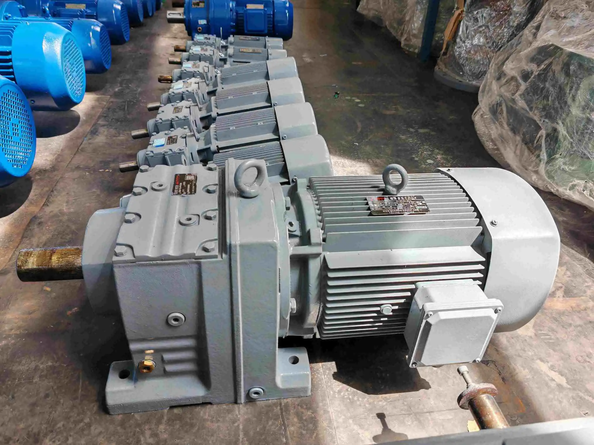
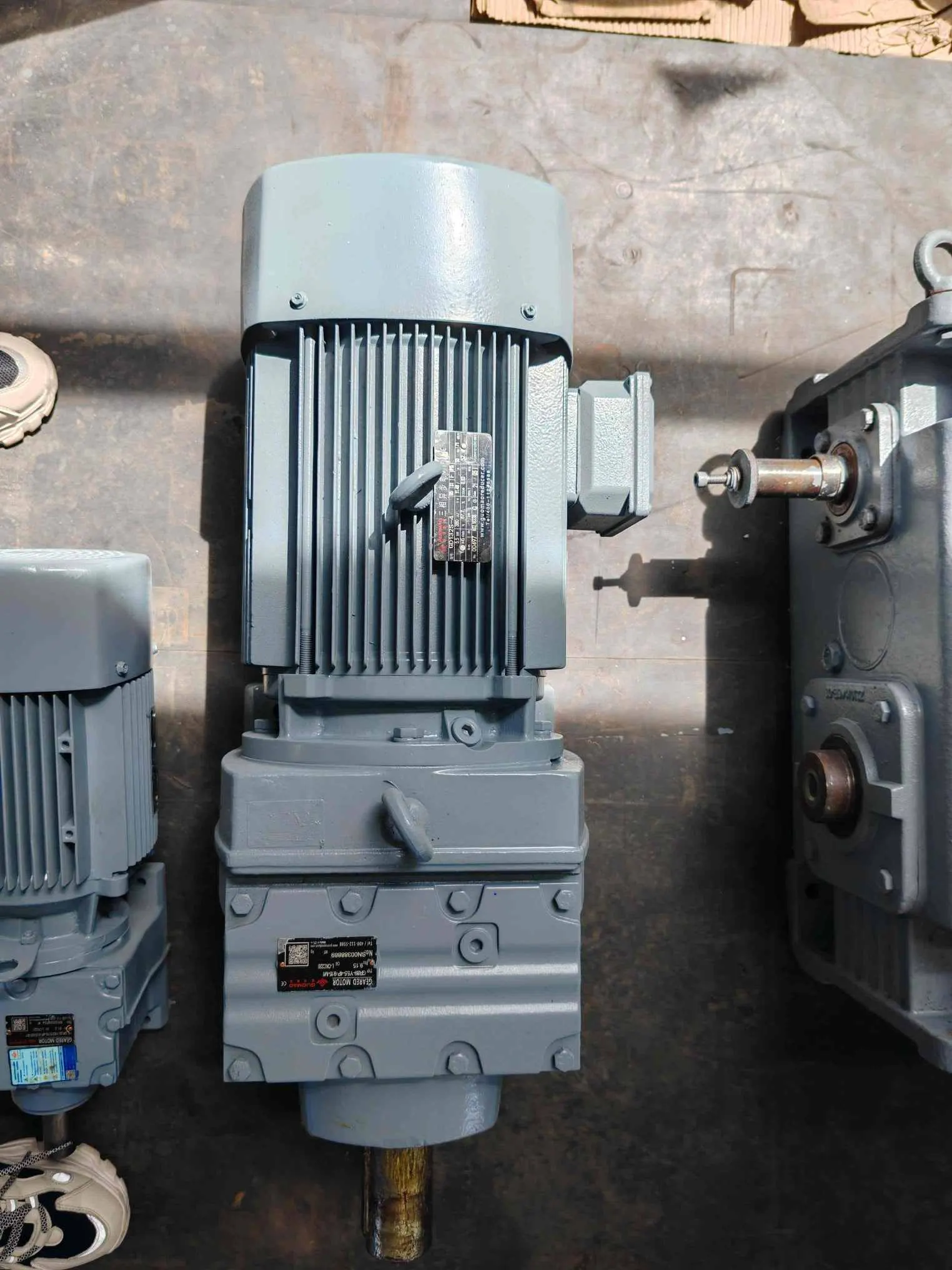
The GR Series Helical Geared Motor is described in the technical material as a modular helical geared unit with small eccentricity between input and output shafts. Its units consist of single-stage, two-stage, or three-stage helical gears, giving engineers room to match the reduction structure to the required speed and torque.
The same record states that the GR type gearbox offers foot-mounted and B5 flange-mounted installations, can be equipped with an extended bearing housing, and offers multiple input shaft configurations. Its published profile lists power of 0.12-200 kW, a ratio of 1.26-33000, and maximum output torque up to 50 kN.m.
The same material identifies a wide range of transmission ratios, rich installation forms, high precision, low noise, high transmission efficiency, small volume, easy maintenance, long service life, and the ability to withstand radial load as product characteristics. These characteristics are useful when the duty cycle includes long running periods, repeated starts, or changing process resistance, but the final selection still depends on the actual load spectrum.
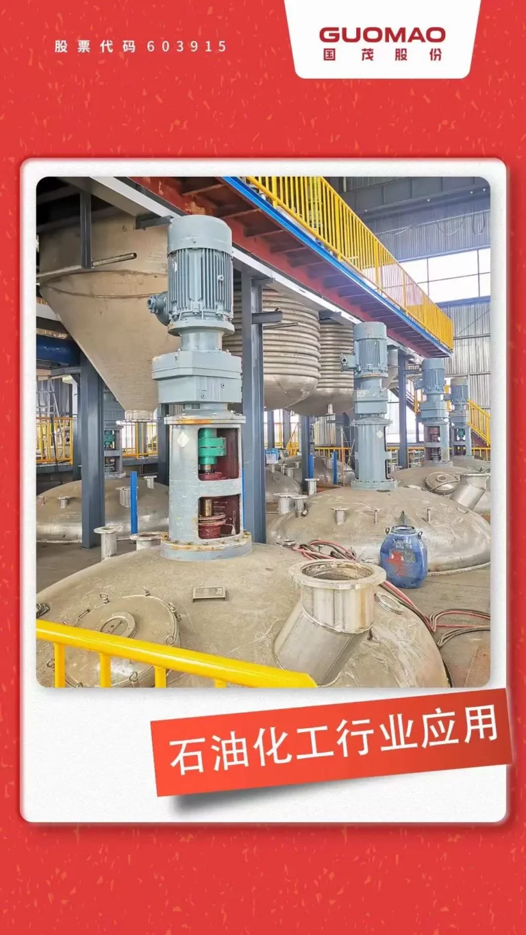
The listed application range includes new energy equipment, charging systems, homogenizing equipment, slurry conveying systems, glue machine systems, hoisting machinery, marching motion, slewing mechanisms, bucket conveyors, screw conveyors, belt conveyors, and winches.
When Duty-Cycle Data Should Trigger Engineering Review
Guomao supports a broader transmission solution range and brings more than 30 years of production and R&D experience to transmission projects. A technically sound selection still begins with complete operating data. We review the machine’s speed, torque, ratio, starts, reversals, inertia, ambient conditions, installation arrangement, and maintenance access before treating a gearbox size as final.
Company scale also matters when a duty cycle is marginal. Guomao’s profile lists 530,000+ square meters of factory area and 400+ million U.S. dollars in annual sales output value, alongside top-quality products and comprehensive technical solutions for operational efficiency and reliability worldwide. Its values include customer oriented, team collaboration, pragmatic and innovative, fair and impartial, and sharing success.
The reducer category page provides a relevant starting point for product and configuration review. Custom engineering attention is especially appropriate when the load includes frequent jams, high inertia, rapid reversals, unusual radial loads, limited cooling space, high ambient temperature, or a duty cycle that differs materially from the catalogue rating conditions.
FAQ
Q: What is a helical reduction gearbox used for?
A: A helical reduction gearbox reduces motor speed while increasing usable output torque for industrial drives. Selection depends on speed, torque, ratio, mounting, shaft loads, and the full duty cycle.
Q: How does a duty cycle affect helical reduction gearbox selection?
A: Duty cycle affects load cycles, heat, peak torque, bearing stress, and service factor. Continuous running, starts, reversals, and shock loads should be evaluated separately.
Q: What should be checked for a continuous-duty helical reduction gearbox?
A: Check continuous torque, thermal capacity, lubricant condition, ambient temperature, airflow, mounting, alignment, and radial or axial loads. A rising temperature trend requires investigation.
Q: Is a higher reduction ratio always better for a helical reduction gearbox?
A: No. A higher ratio may provide more torque, but it can increase heat or require more stages. The ratio should match the driven machine’s speed window and process requirement.
Q: When should a helical reduction gearbox receive a custom engineering review?
A: A review is recommended for high inertia, frequent starts or reversals, shock loading, jams, high ambient temperature, restricted cooling, unusual shaft loads, or nonstandard mounting.