


Selecting a cycloidal reducer for demanding duty requires more than matching motor power and reduction ratio. A drive that starts loaded, reverses repeatedly, runs 16 or 24 hours per day, or carries a belt or sprocket load can require a larger specification than average torque suggests. Shock load, starts per hour, radial load, temperature, dust, humidity, mounting, and required reliability all change the service margin. Selection must begin with the real operating cycle, separate running torque from startup and temporary peak torque, and check thermal, lubrication, shaft-load, and installation conditions.
Why Demanding Industrial Duty Changes Cycloidal Reducer Selection
How Shock Loads, Frequent Starts, and Reversing Duty Increase the Required Service Margin
A loaded start accelerates machine inertia while overcoming process resistance. Variable torque and impact add peaks hidden by an average-load calculation. Reversing repeats acceleration through zero speed and changes force direction. Guomao describes its cycloidal reducer as having strong overload capacity, impact resistance, and small inertia, with suitability for frequent starting and forward/reverse rotation. Our selection process must still quantify severity, frequency, and peak torque.
How Continuous Operation and Harsh Conditions Change Thermal and Lubrication Requirements
An 8-hour shift, 16-hour schedule, and 24-hour system impose different accumulated duty. The source states suitability for a 24-hour working system, while lubrication still depends on model, stage count, installation, and ambient conditions. Temperature, dust, and humidity require checks of lubricant, oil level, sealing, inspection, and heat dissipation. A mechanical rating alone does not prove thermal suitability.
What Operating Data Should Be Defined Before Selecting a Cycloidal Reducer?
Determine Motor Power, Input Speed, Required Output Speed, and Reduction Ratio
Record motor power, fully loaded motor speed, target output RPM, and the available standard ratios. For initial cycloidal reducer sizing:
required ratio ≈ input speed ÷ target output speed
Match this target to a standard ratio, recalculate output speed, and confirm that the process accepts the difference.
Define Running Torque, Peak Torque, and Load Characteristics
Running torque describes sustained load. Startup torque covers acceleration and loaded starts. Peak torque covers jams, impacts, material changes, or short overloads. Motor power is only an entry parameter; final checks require output torque, peak torque, service margin, and load pattern.
Record Daily Operating Hours and Start-Stop Frequency
Document hours per day and count each start and stop as one event. Record reversals, driven inertia, and whether starting occurs empty or loaded. These values feed the working-condition calculation.
How Do Service Factor and Torque Determine the Correct Cycloidal Reducer Size?
Calculate the Actual Working Condition Factor Before Choosing a Model
Combine Load Characteristics and Operating Hours
The Guomao selection method uses fA = fAh × fAc. The factor fAh combines driven-machine load characteristics with daily operating hours. A mixer with uneven density, for example, should not use the same fAh basis as a smoothly loaded feeder.
Adjust for Start-Stop Frequency, Temperature, and Reliability Requirements
The source assigns fAc values of 1.00 below 10 starts/stops per hour, 1.15 below 100, and 1.25 below 500. High temperature may require fAt, while high reliability may require fAs. Frequent reversing or unusual conditions need application-specific confirmation.
Verify the Cycloidal Reducer Service Coefficient Against the Required Working Condition Factor
The central model check is:
fB ≥ fA
Here, fB is the reducer service coefficient and fA is the calculated working condition. If the model fails this inequality, increase its size. The verified Cycloidal Reducer page identifies the range, but the current selection table and duty calculation determine the specification.
Check Output Torque and Peak Torque Instead of Selecting by Motor Power Alone
After the coefficient check, verify catalog output torque against required running torque and confirm permissible peak behavior for startup and temporary overloads. Where a preliminary selection passes by motor power but lacks torque or service margin, it is not complete.
How Should Reduction Ratio and Stage Count Be Selected for a Cycloidal Reducer?
Match Motor Speed to the Required Output RPM
For cycloidal reducer ratio calculation, divide input speed by target output speed, choose the nearest suitable standard ratio, and calculate the resulting output RPM. Do not begin with a convenient stock ratio and force the machine process to accept an unsuitable speed.
When Should a Single-Stage or Multi-Stage Cycloidal Reducer Be Used?
The approved single-stage ratio range is 7-87. Higher ratios use two-stage or three-stage combinations when one stage cannot reach target speed. Stage count follows required ratio, not an assumption that more stages are better. Cycloidal gear reducer development provides application context; actual selection remains tied to the catalog.
Why Very High Reduction Ratios Still Require Efficiency and Operating-Condition Checks
A very high ratio reduces speed, but added stages change efficiency, heat, lubrication, size, and starting behavior. Recheck output torque and continuous duty.
How Do Radial Loads and Mounting Conditions Affect Cycloidal Reducer Selection?
Verify Radial Load from Sprockets, Pulleys, Belts, and Gears
Calculate the Actual Radial Load Created by the Driven Element
Use Fr = Mr × fr / r, where Mr is working torque, r is pitch radius, and fr is the radial-load factor.
| Driven element | Radial-load factor fr |
| Single-row sprocket | 1.0 |
| One gear or double-row sprocket | 1.25 |
| V-belt | 1.5 |
| Flat belt | 2.5 |
At the shaft-extension midpoint, verify fA × Fr ≤ Fra.
Correct the Allowable Radial Load for the Actual Load Position on the Shaft
Fra is not automatically valid everywhere on the shaft extension. At the shaft end, multiply table Fra by 0.4. For other positions, calculate Fx from the source formulas using distance X and extension length L, then verify fA × Fr ≤ Fx. This radial load position correction can change the required model even when torque is acceptable.
Match Mounting Type, Shaft Connection, and Coupling Alignment
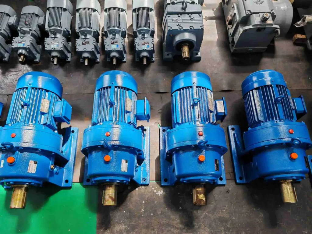
A foot-mounted cycloidal reducer requires a solid horizontal support. A flange-mounted cycloidal reducer changes installation and lubrication considerations. Coupled shafts must remain within permitted coaxiality; gear or sprocket connections require parallel shaft axes. An overly loose sprocket drive can create startup impact.
Check Foundation Stability and Installation Geometry
Mounting is a mechanical condition. Confirm foundation rigidity, vibration, shaft direction, lubrication access, and connection geometry. Trial-run without load, then load gradually.
How Do Different Demanding Applications Change Cycloidal Reducer Selection Priorities?
Mixers and Agitators: Variable Torque, Loaded Starts, and Continuous Duty
Viscosity and density variation change running and startup torque. Translate that variation into load characteristics, loaded-start demand, operating hours, and fA before choosing model size.
Conveyors and Material Handling: Loaded Starts, Radial Loads, and Shock Conditions
Conveyors may start with material already on the belt. Pulley, sprocket, or belt forces then require radial-load verification as well as torque and shock checks. The practical selection logic complements Guomao’s discussion of cycloidal reducers in material handling systems.
Frequent-Cycling and Reversing Equipment: Start Frequency, Inertia, and Overload Protection
Count starts, stops, and reversals; identify driven inertia and peak torque; apply fAc; and confirm overload protection where overload can occur. Small reducer inertia can help the drive respond, but it does not replace system-level acceleration and protection checks.
FAQ
Q: What size cycloidal reducer do I need for a heavy-duty application?
A: Calculate ratio, running torque, startup and peak torque, fA, operating hours, starts per hour, radial load, and mounting conditions. Choose a model that satisfies fB ≥ fA and all torque and shaft-load limits.
Q: What service factor should I use when selecting a cycloidal reducer?
A: There is no single value for every machine. Determine it from load severity, daily hours, start-stop frequency, temperature, reversals, inertia, and reliability requirements, then use the current manufacturer table.
Q: How do I calculate the reduction ratio for a cycloidal reducer?
A: Divide fully loaded input speed by target output RPM, match the result to a standard ratio, and recalculate actual output speed before confirming the stage count.
Q: Can a cycloidal reducer handle frequent start-stop and reversing duty?
A: The Guomao source states suitability for frequent starts and forward/reverse operation. Selection must still include fAc, startup torque, inertia, thermal conditions, and overload protection.
Q: How do I check radial load when selecting a cycloidal reducer?
A: Calculate Fr from working torque, pitch radius, and the driven-element factor. Apply fA, correct allowable load for the actual shaft position, and verify fA × Fr does not exceed Fra or Fx.