

A conveying system may appear mechanically simple, but its drive must handle changing resistance, material impact, loaded starts, long operating hours, and occasional blockages. Selecting a reducer only by motor power can result in insufficient starting torque, incorrect conveyor speed, excessive shaft loading, or premature wear.
A correctly selected cylindrical gear reducer converts motor speed into the controlled output speed and torque required by the conveyor. Its performance depends on transmission ratio, conveyor duty, material characteristics, installation accuracy, ambient temperature, and lubrication conditions.
Why Is a Cylindrical Gear Reducer Suited to Conveyor Drive Systems?
How Does a Cylindrical Gear Reducer Support Conveyor Operation?
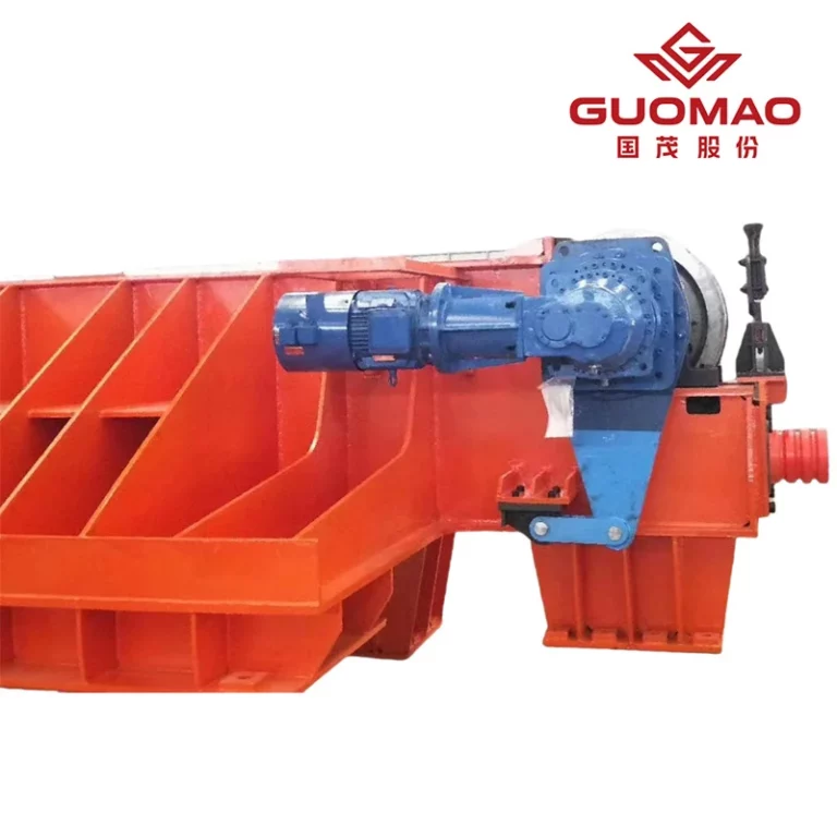
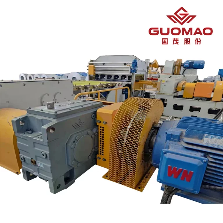
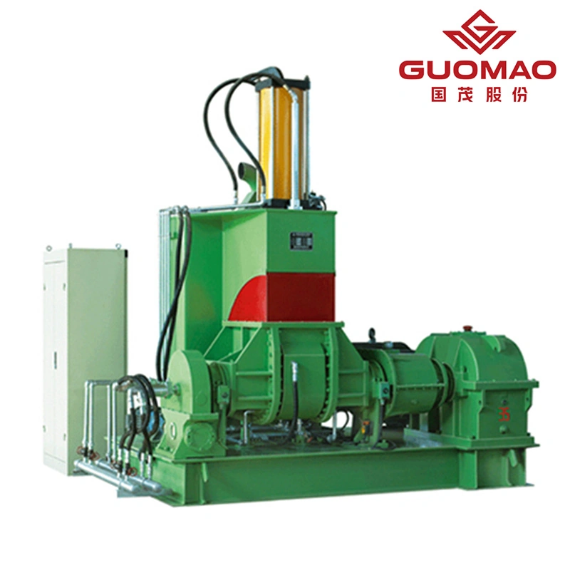
A cylindrical gear reducer reduces the rotational speed supplied by the motor and converts it into the higher output torque required to drive conveyor equipment. Depending on the required transmission ratio, the reducer may use one or more gear stages to maintain a stable output speed under continuous conveying loads, loaded starts, and changing material resistance.
Its performance depends heavily on gear strength, tooth accuracy, contact quality, and heat-treatment consistency. These factors influence load capacity, operating noise, transmission stability, and service life in belt conveyors, bucket conveyors, and other material-handling systems.
The gears used in Guomao’s ZY Series Cylindrical Gear Reducer are manufactured from high-strength low-carbon alloy steel. Carburizing and quenching produce a tooth-surface hardness of HRC58–62, while precision gear grinding improves contact accuracy and smooth engagement.
Key characteristics include:
1.High load-bearing capacity
2.Low operating noise
3.Compact size and low weight
4.Long service life
5.Easy installation and maintenance
6.Stable transmission under continuous duty
Transmission efficiency is approximately 98% for a single-stage arrangement, 96% for a two-stage arrangement, and more than 95% for a three-stage arrangement.
Which Conveyor Loads Benefit from a High-Torque Drive?
A high-torque conveyor drive is required when the conveyor starts under load, lifts material vertically, operates on an incline, or experiences irregular material flow.
Typical applications include:
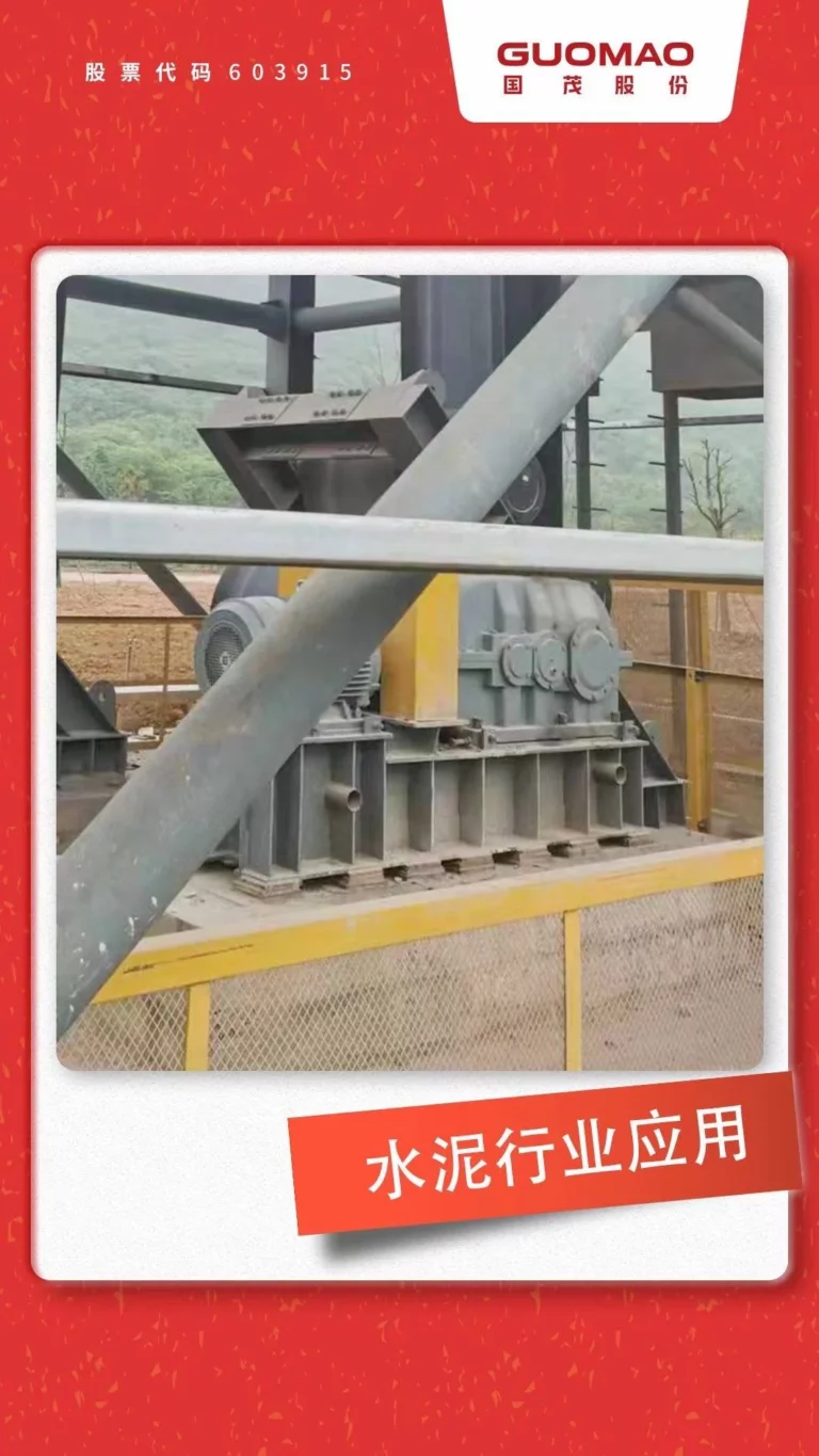
1.Belt conveyors for ores, coal, cement, and raw materials
2.Bucket conveyors for vertical lifting
3.Material transport systems in metallurgy
4.Continuous-duty conveying equipment
5.Conveyors operating in dusty or low-temperature environments
In these conditions, the reducer must maintain a stable output speed while limiting excessive tooth stress, vibration, and temperature rise.
How Do You Size a Cylindrical Gear Reducer for a Conveyor?
How to Calculate Conveyor Output Speed and Gear Ratio
The first step in cylindrical gear reducer selection is determining the required reducer output speed.
For a belt conveyor:
Pulley speed (rpm) = 60 × belt speed (m/s) ÷ [π × pulley diameter (m)]
The required transmission ratio is:
Transmission ratio = motor speed ÷ reducer output speed
For example, if a motor runs at 1,480 rpm and the pulley must rotate at 74 rpm:
1,480 ÷ 74 = 20
This conveyor gearbox ratio calculation gives the theoretical ratio. The nearest available nominal ratio must then be selected, and the actual conveyor output speed recalculated.
A small speed difference may affect conveyor capacity and process coordination. Therefore, the reduction ratio for belt conveyor applications should be checked against both mechanical and production requirements.
How to Calculate Running Torque and Starting Torque
Running torque is the torque required after the conveyor reaches normal speed. It depends on material weight, friction, conveyor inclination, and mechanical losses.
A simplified output torque relationship is:
Torque (N·m) = 9,550 × power (kW) ÷ output speed (rpm)
However, motor power alone is not enough for final selection.
Design torque should consider:
- Normal running resistance
- Material loading rate
- Conveyor inclination
- Loaded startup
- Acceleration time
- Material blockage
- Drive pulley diameter
- External mechanical losses
Starting torque may be much higher than running torque, especially for inclined belt conveyors and loaded bucket conveyors. A reducer selected only from steady-state torque may be undersized during startup.
How Should Service Factor Reflect Conveyor Duty?
The service factor adjusts nominal reducer capacity according to actual working severity.
Important variables include:
| Operating condition | Effect on reducer selection |
| Longer daily operating time | Increases accumulated gear and bearing duty |
| Frequent starts and stops | Increases repeated acceleration loads |
| Loaded starting | Raises peak torque demand |
| Uneven material flow | Produces fluctuating tooth loads |
| Material blockage | May create short-duration overload |
| Inclined conveying | Adds continuous gravitational resistance |
| Reversing operation | Changes load direction and contact conditions |
A fixed factor should not be used for every belt conveyor gearbox. Operating hours, load characteristics, and starts per hour must all be reviewed.
How Does the Number of Gear Stages Affect Selection?
Our ZY Series includes:
- ZDY single-stage cylindrical gear reducer
- ZLY two-stage cylindrical gear reducer
- ZSY three-stage cylindrical gear reducer
- ZFY four-stage cylindrical gear reducer
Fewer stages are generally considered for lower ratios, while more stages support higher total ratios. Stage count also affects efficiency, dimensions, lubrication, and installation space.
The final arrangement must satisfy ratio, power, torque, and duty requirements.
How Should a Cylindrical Gear Reducer Match Different Conveying Applications?
Cylindrical Gear Reducers for Belt Conveyors
A cylindrical gear reducer for belt conveyor duty must provide a stable pulley speed while accommodating both continuous resistance and startup demand.
Required selection data include:
- Belt speed
- Pulley diameter
- Conveyor length and inclination
- Maximum loading
- Bulk density
- Motor power and speed
- Operating hours
- Starting method
- Starts per hour
A heavy-duty belt conveyor gearbox used for ore or coal transport must also withstand load fluctuations caused by material impact at transfer points.
Where reverse movement may occur on an inclined conveyor, a backstop may be required. When a backstop is fitted, the reducer can operate only in the specified direction.
Cylindrical Gear Reducers for Bucket Conveyors
A bucket conveyor gearbox must continuously lift the material, buckets, chains, or belts, and rotating components. Gravity remains part of the operating load throughout the lifting cycle.
Critical conditions include:
- Full buckets during startup
- Material in the boot section
- Reverse rotation after shutdown
- Uneven feeding
- Material buildup
- Repeated stop-start operation
Design torque should therefore reflect loaded startup rather than empty-machine operation.
Cylindrical Gear Reducers for Bulk Material Handling
In bulk material handling, the material name alone is not enough for reducer selection. Ore, coal, clinker, cement, and raw stock create different loads depending on density, moisture content, particle size, conveyor incline, and feeding consistency.
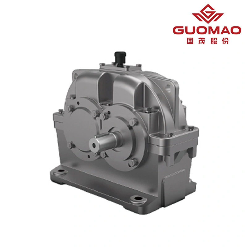
A mining conveyor reducer may also face abrasive dust, outdoor temperature changes, and high starting resistance. These conditions must be included in the selection process.
Which Mechanical and Site Conditions Must Be Verified?
Check Speed, Rotation Direction, and Operating Temperature
For the ZY Series Cylindrical Gear Reducer, the documented limits include:
| Parameter | Operating condition |
| Maximum high-speed shaft speed | 1,500 rpm |
| Maximum gear circumferential speed | 20 m/s |
| Ambient temperature | -40°C to +45°C |
| Rotation | Both directions unless a backstop is fitted |
When the ambient temperature is below 0°C, lubricating oil should be heated before startup. Excessively viscous oil can restrict lubrication and increase startup resistance.
Applications outside these limits require technical review.
Verify Shaft Loads, Alignment, and Foundation Rigidity
A reducer may satisfy torque requirements but still fail prematurely if installation loads are ignored.
Check:
- Radial loads from pulleys, gears, or sprockets
- Load position on the shaft
- Coupling alignment
- Shaft parallelism
- Foundation flatness and rigidity
- Bolt tightening
- Maintenance access
Couplings, pulleys, and sprockets should not be installed by hammering, as impact can damage bearings and shaft surfaces.
How Does the ZY Series Support Conveyor Applications?
At Guomao, our ZY Series is designed as an external-meshing, parallel-shaft cylindrical gear reducer for high-load conveying applications.
Its documented range is:
| Selection parameter | ZY Series range |
| Power | 1.1–6,000 kW |
| Speed ratio | 1.25–500 |
| Maximum output torque | Up to 950 kN·m |
| Gear material | High-strength low-carbon alloy steel |
| Tooth-surface hardness | HRC58–62 |
| Confirmed uses | Belt conveyors, bucket conveyors, ore conveying, raw-material transport |
Before final selection, users should provide:
- Motor power and speed
- Required conveyor speed
- Pulley or shaft diameter
- Operating and starting torque
- Conveyed material and capacity
- Conveyor length and inclination
- Daily operating time
- Starts per hour
- Ambient temperature
- Rotation direction
- Installation position
- Backstop requirement
How Should a Conveyor Cylindrical Gear Reducer Be Installed and Maintained?
Installation and Commissioning Checks
Before startup, verify foundation rigidity, shaft alignment, fasteners, rotation direction, and oil level. The reducer should first run without load to distribute lubricant across gears and bearings.
Load should then be applied gradually while monitoring:
- Noise
- Vibration
- Bearing temperature
- Housing temperature
- Oil leakage
- Motor current
- Conveyor speed
Immediate full-load operation may hide alignment or lubrication problems until damage develops.
Conveyor Gear Reducer Maintenance Indicators
Effective conveyor gear reducer maintenance focuses on condition trends rather than waiting for failure.
Inspect regularly for:
- Changes in gear noise
- Increasing vibration
- Oil leakage
- Loose foundation bolts
- Coupling wear
- Abnormal temperature
- Contaminated lubricant
- Dust accumulation
A gradual rise in vibration or temperature often provides an earlier warning than sudden failure.
FAQ
Q: What transmission ratio should a cylindrical gear reducer use for a conveyor?
A: The ratio equals motor speed divided by the required conveyor shaft speed. The nearest nominal ratio should be selected, followed by recalculation of the actual output speed.
Q: Can a cylindrical gear reducer handle loaded conveyor starts?
A: Yes, when the reducer is selected for the actual starting torque. Conveyor incline, material buildup, acceleration time, and loaded startup must be included in the design load.
Q: Can a cylindrical gear reducer operate in both directions?
A: The ZY Series can operate in both directions under standard conditions. When a backstop is installed, operation is limited to the specified direction.