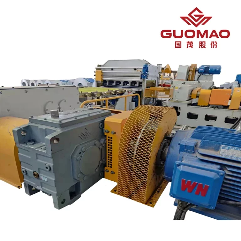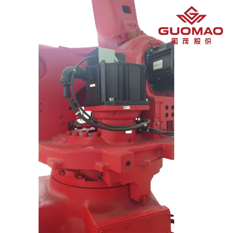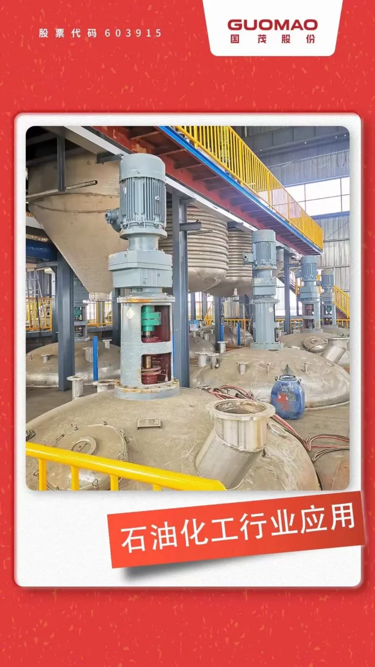



Una caja de engranajes para maquinaria pesada rara vez experimenta un par constante. Puede funcionar, acelerar con alta inercia, invertir el sentido de giro y absorber un atasco. El dimensionamiento comienza con el historial de carga, no con la potencia del motor. La tensión en los dientes, la carga en los cojinetes, la deflexión del eje y el calor deben mantenerse dentro de los límites.
¿Por qué las cargas combinadas de impacto y continuas son tan exigentes para una caja de cambios en maquinaria pesada?
¿En qué se diferencian las cargas de choque de las cargas continuas y cíclicas?
La carga continua mantiene el contacto entre los dientes, la carga del cojinete y el calor. La carga cíclica repite las transiciones o los cambios de par. El impacto es un evento rápido que puede elevar la tensión local por encima del promedio móvil y provocar holgura, torsión del eje y vibración de la carcasa.
¿Qué operaciones con maquinaria pesada generan cargas combinadas severas?
Las grúas de elevación, las mezcladoras, los molinos, las trituradoras, los polipastos y las cintas transportadoras merecen una revisión porque combinan largos períodos de funcionamiento con inercia, perturbaciones del proceso o aumentos repentinos de material. Esta guía para fiabilidad de la caja de engranajes de la cinta transportadora Ofrece contexto, pero los datos medidos de la máquina deben controlar la selección.
¿Qué ocurre cuando los impactos repetidos no dejan tiempo de enfriamiento ni de recuperación?
Los impactos repetidos reducen el margen de fatiga, mientras que el funcionamiento continuo mantiene el aceite caliente. La inercia térmica retrasa el enfriamiento y las cargas de los cojinetes pueden superponerse. La fatiga mecánica y la capacidad térmica deben evaluarse conjuntamente.
¿Cómo se deben convertir las cargas combinadas en un espectro de carga de la caja de cambios?
Construya el espectro completo de carga operativa.
Registre el par motor, la velocidad, la dirección, la duración, la frecuencia y la temperatura. Separe el funcionamiento normal, las transiciones y los eventos excepcionales para que el espectro represente el funcionamiento real.
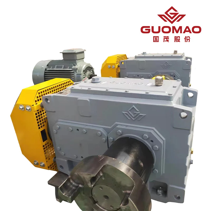
Par de funcionamiento continuo y ciclo de trabajo diario
Registre las horas en cada punto de par-velocidad, porcentaje de carga, temperatura ambiente y refrigeración o lubricación activa. La idoneidad para servicio continuo indicada para un producto no se puede transferir a todas las familias de reductores.
Par de arranque, aceleración y marcha atrás
Mida el par motor y el tiempo durante el arranque, la aceleración, el frenado y la marcha atrás. La inercia de carga reflejada y el par de aceleración disponible determinan el tiempo de transición, por lo que un par motor moderado puede enmascarar un transitorio severo.
Par máximo, par de atasco y par de emergencia
Enumere por separado los picos del proceso, los eventos de bloqueo de salida, las paradas de emergencia y las activaciones del limitador de par. Registre la magnitud, la duración, la frecuencia y si la respuesta prevista es la supervivencia, la desconexión o el apagado controlado.
Aplicar factores de servicio para impacto y servicio continuo.
Severidad de la carga, horas de funcionamiento y frecuencia de choque
Utilice el método del fabricante para combinar la severidad, las horas de funcionamiento, las transiciones y la frecuencia de impacto. La corrección de temperatura y los factores de seguridad pueden introducirse por separado. No transfiera un coeficiente de catálogo a otra máquina o familia de máquinas.
Arranques, paradas, inversiones e inercia de la máquina accionada
Contabilice las transiciones por turno e incluya la inercia del motor más la inercia de la carga referida al eje. El par motor utilizado para acelerar la inercia no está disponible para un impacto que se produzca durante esa transición.
Determinar si la capacidad mecánica o térmica controla el tamaño de la caja de engranajes.
Verifique los dientes, cojinetes, ejes, acoplamientos y cargas externas. Compruebe por separado la pérdida de potencia, la disipación de calor, la temperatura del aceite y la refrigeración. El margen de seguridad inferior es determinante para el tamaño; el par motor por sí solo no es suficiente.
¿Qué características de diseño de la caja de cambios resisten los golpes, la fatiga y el calor?
Materiales de engranajes endurecidos y calidad de contacto de los dientes
La resistencia a los impactos depende del material, el tratamiento térmico, la geometría, la alineación y la distribución de la carga. Una superficie dentada dura mejora la resistencia al desgaste y al contacto, pero no puede compensar la sobrecarga, la lubricación deficiente ni la deflexión del eje.
Dientes de engranaje carburizados y templados
La especificación ZY indica acero aleado de bajo contenido de carbono y alta resistencia, carburización y temple. La especificación HB describe forjas de acero carburizado y tratamiento térmico controlado. Estas son características del producto, no una prescripción universal de materiales.
Rectificado de precisión y distribución de la carga en toda la superficie del diente.
El rectificado y la modificación del perfil mejoran la precisión y la calidad del contacto. La distribución real de la carga frontal sigue dependiendo de los ejes, los cojinetes, la rigidez de la carcasa y la alineación, por lo que la puesta en marcha debe incluir una comprobación del patrón de contacto.
Capacidad de carga, deflexión del eje y rigidez de la carcasa.
Los cojinetes soportan fuerzas de engranaje, cargas en voladizo y par transitorio. El movimiento del eje o de la carcasa puede concentrar el contacto de los dientes en un borde. Una base rígida forma parte de la trayectoria de carga; corriente Caja de cambios industrial vertical B Los detalles deben coincidir con la orientación final y las cargas del eje.
Lubricación, refrigeración y sellado para cajas de engranajes de servicio continuo
Seleccione el aceite, los sellos, los ventiladores y la circulación adecuados para el modelo, la posición de montaje, la velocidad, la temperatura ambiente y el ciclo de trabajo. Supervise el estado, la temperatura y las fugas del aceite. Mantenga los grados, presiones y caudales especificados en el manual dentro del alcance indicado para el producto.
¿Cómo debe adaptarse una caja de cambios para maquinaria pesada al perfil de carga?
Cajas de engranajes industriales para servicio continuo de alto par y cargas máximas severas.
Las cajas de engranajes industriales son adecuadas para alto par, largas horas de funcionamiento y refrigeración, sellos o montaje configurables. El material fuente de Guomao describe la verificación de fatiga HB y los engranajes rectificados. Nuestros ingenieros deben comparar el espectro medido con la unidad seleccionada; la actual Caja de engranajes industrial en H-Paralelo Esta página es una referencia, no una selección completa.
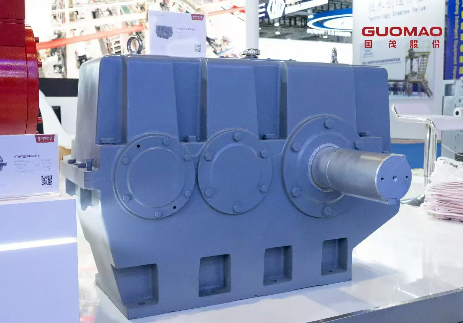
Reductores de engranajes cilíndricos de superficie dura para cargas de procesamiento repetitivas
ZY es una opción cilíndrica con superficie dentada endurecida y engranajes carburizados, templados y rectificados. Entre sus aplicaciones se incluyen equipos para metalurgia, carbón, elevación, transporte y cemento. Confirme la temperatura, la lubricación y las cargas del eje para la unidad seleccionada.
Motorreductores helicoidales de ejes paralelos para accionamientos compactos con control de impacto
GF utiliza dos o tres etapas helicoidales de ejes paralelos con diversas configuraciones de montaje y eje de salida. Es adecuado para sistemas compactos de transporte, elevación o accionamiento de cabrestantes cuando el control de impactos se realiza mediante el accionamiento y el acoplamiento. No debe considerarse una solución de extrusión de plástico o caucho.
¿Cómo puede el sistema de transmisión reducir los impactos antes de que lleguen a la caja de cambios?
Utilice acoplamientos flexibles y dispositivos limitadores de par.
Utilice la flexibilidad de acoplamiento adecuada para compensar errores de alineación y amortiguar perturbaciones torsionales. Un limitador de par puede limitar el par o interrumpir su flujo durante un atasco. Coordine el par de disparo y el comportamiento de reinicio con los picos normales, el par admisible de la caja de engranajes y la seguridad del proceso.
Controla la aceleración, la marcha atrás y el frenado con un variador de frecuencia o un arrancador suave.
Un variador de frecuencia (VFD) puede controlar la aceleración, la desaceleración, la inversión de giro y la respuesta de par cuando los ajustes reflejan los datos del motor, la inercia de la carga, el frenado y la resonancia. Un arrancador suave puede reducir el paso de arranque, pero ninguno de estos dispositivos reemplaza la verificación del espectro de carga.
Mejora la rigidez de la cimentación, la alineación del eje y la distribución de la carga.
Utilice una base rígida y sin vibraciones; ajuste la coaxialidad del acoplamiento y el paralelismo de los engranajes o piñones; y elimine la holgura que pueda provocar un impacto inicial. Vuelva a comprobar los pernos, las arandelas, la alineación y los patrones de contacto tras la primera prueba con carga y tras la estabilización térmica.
Compruebe las cargas radiales, axiales y en voladizo en el eje de la caja de engranajes.
Calcule la carga radial en la posición real del engranaje, polea o piñón. Añada el empuje axial, la tensión de la correa o cadena, la distancia de voladizo y la dirección transitoria, y compare el resultado con los límites de la caja de engranajes, el eje, el cojinete y el acoplamiento.
¿Cómo pueden los ingenieros verificar que la caja de cambios tenga el tamaño correcto?
Utilice la puesta en marcha por etapas para confirmar el comportamiento de la carga y la temperatura.
Realice la prueba sin carga, luego con carga parcial y finalmente con la carga prevista. Aumente la carga gradualmente mientras registra el par, la temperatura, la vibración, el ruido y el estado de lubricación o refrigeración. Investigue las tendencias anómalas antes de realizar las pruebas de carga máxima.
Monitorear la temperatura del aceite, la vibración, el ruido y el estado del lubricante.
Establezca una línea base estable en ubicaciones consistentes. El aumento de temperatura, el ruido de la malla, la vibración, las fugas o los residuos pueden indicar sobrecarga, desalineación, daños en los cojinetes o los dientes, o fallas en el sistema de refrigeración.
Compare el par máximo real con el espectro de carga de diseño original.
Utilice registros de conducción, instrumentos de torsión o registros de eventos para localizar picos. Compare la magnitud, la duración y la frecuencia con el espectro de diseño y, si los impactos, las inversiones o la inercia superan los supuestos, vuelva a revisar la selección.
Defina los límites de advertencia para la inspección, la reducción de carga y la parada.
Defina tres respuestas: inspeccionar y analizar tendencias, reducir la carga o la velocidad y apagar el sistema. Los límites numéricos deben provenir de la caja de engranajes, el lubricante, los cojinetes, los sensores, las condiciones ambientales y una línea base verificada del sitio.
Preguntas frecuentes
P: ¿Qué factor de servicio debe utilizar una caja de cambios para maquinaria pesada bajo cargas de choque repetidas?
R: No existe un valor universal que sea seguro. Calcúlelo a partir de la severidad, las horas de funcionamiento, las transiciones, la inercia, la frecuencia de impacto, las condiciones ambientales y la fiabilidad requerida, y luego confirme que la caja de engranajes seleccionada supera dicho requisito de servicio.
P: ¿Cómo se dimensiona una caja de cambios para maquinaria pesada para un funcionamiento continuo las 24 horas del día, los 7 días de la semana?
A: Construya el espectro par-velocidad-tiempo y verifique los dientes, cojinetes, ejes, cargas externas, capacidad térmica, refrigeración y lubricación. La idoneidad para un producto no se puede transferir a toda la familia.
P: ¿Qué diseño de engranajes es el mejor para una caja de cambios destinada a maquinaria pesada sometida a impactos y par variable?
A: Seleccione entre todo el espectro de cargas. Los engranajes endurecidos y rectificados con precisión son útiles, pero la capacidad de carga, la alineación, la rigidez de la carcasa, la lubricación y el control de impactos aguas arriba siguen siendo igualmente importantes.
P: ¿Cómo se puede prevenir el sobrecalentamiento en una caja de cambios para maquinaria pesada que funciona de forma continua?
A: Verifique la capacidad térmica en funcionamiento real y, a continuación, ajuste el aceite, los sellos, los ventiladores, la circulación y las condiciones ambientales. Registre la tendencia de la temperatura desde el arranque hasta el estado estacionario.
P: ¿Qué señales de advertencia indican que una caja de cambios para maquinaria pesada está sufriendo daños por sobrecarga?
A: Los nuevos ruidos de impacto o de engranaje, el aumento de la vibración, los residuos de lubricante, las fugas, la temperatura anormal, el movimiento del eje, el montaje flojo y las repetidas activaciones del limitador son señales de advertencia. Confirme la causa antes de reanudar el funcionamiento normal.