Cylindrical Gear Reducer Efficiency Fundamentals in Industrial Power Transmission
How Cylindrical Gear Reducer Efficiency Is Defined in Engineering Terms
Cylindrical Gear Reducer efficiency is defined as the ratio of output mechanical power to input power under specified load and speed conditions. In practical engineering, this value reflects cumulative losses caused by gear meshing friction, bearing resistance, lubricant drag, and thermal effects. Because most industrial cylindrical gear reducers operate continuously, even small efficiency differences translate into measurable energy cost changes over a year of operation.
Efficiency gets trickier in multi-step setups. Losses build up one after another. One step at 98% efficiency might give about 94–95% total in a three-step unit. This buildup shows why gear accuracy, steady alignment, and bearing strength matter. They keep actual work near planned numbers.
Transmission efficiency also depends on torque, speed, and friction characteristics. Higher torque increases contact stress, while higher pitch line velocity elevates churning and sliding losses. Therefore, accurate load calculation according to recognized standards is essential for predicting operational efficiency rather than relying solely on catalog data.
Typical Efficiency Benchmarks of Industrial Cylindrical Gear Reducer Systems
Industrial cylindrical gear reducer systems typically outperform worm gear designs in mechanical efficiency because helical gear meshing relies primarily on rolling contact. Under nominal load, a single-stage helical cylindrical gear reducer can achieve up to 98% efficiency. Two-stage systems often maintain 95–96%, and three-stage systems remain above 94% when properly optimized.
| Configuration | Approx. Efficiency | 典型应用 |
| Single-stage helical | 97–98% | 输送机 |
| Two-stage helical | 95–96% | Lifting systems |
| Three-stage helical | 94–95% | 采矿业 |
| Worm gear | 85–90% | Low-speed drives |
For this reason, cylindrical gear reducer setups work well in tough fields like metal work, cement making, and bulk goods moving. Non-stop use makes efficiency differences hit costs hard.
Why Efficiency Directly Impacts Energy Consumption and Thermal Stability
Cylindrical Gear Reducer efficiency shapes heat inside. Lost power turns to warmth. This lifts oil heat and speeds oil breakdown. Too much heat breaks the oil’s thickness. Then, lubrication weakens, and the rub grows.
Energy models show clear gains. In a 200 kW setup running 6,000 hours a year, a 2% efficiency boost saves lots of power. So, efficiency now leads talks in new factory growth. It shows at big shows like CONEXPO-CON/AGG 2026. There, green use and power fixes stand out.
Mechanical Design Factors That Influence Cylindrical Gear Reducer Efficiency
Gear Tooth Geometry and Surface Hardening in Cylindrical Gear Reducer Design
Gear shape in cylindrical gear reducer design sets load spread and slide rub. Helical gears give better contact share. This allows even torque pass and less spot stress than straight spur gears.
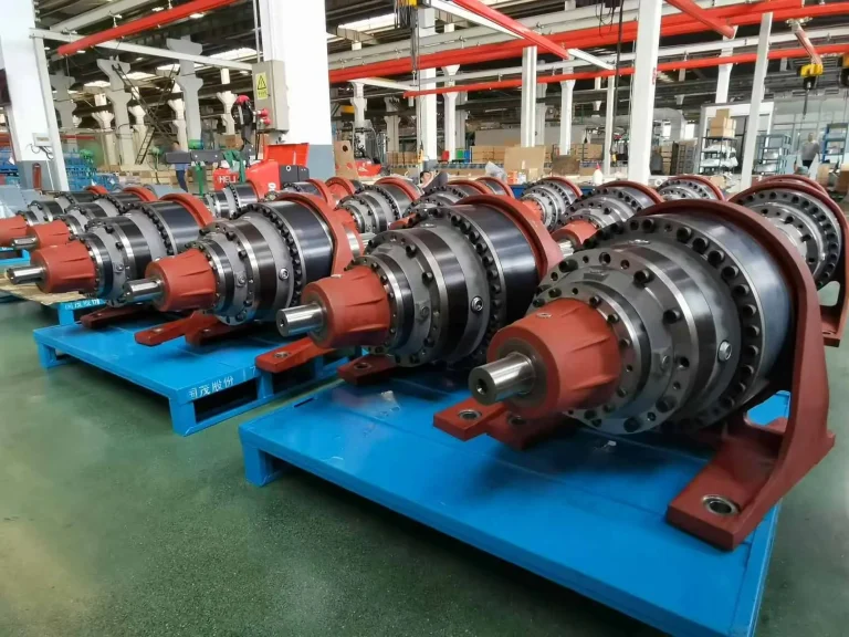
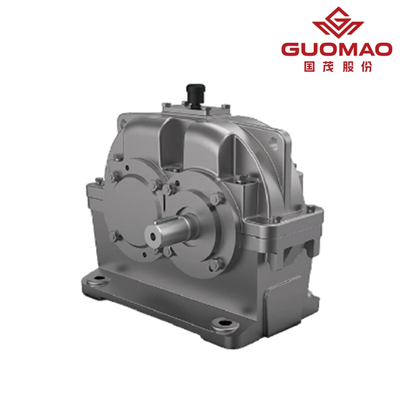
Hardening the surface keeps efficiency steady over time. In the ZY系列圆柱齿轮减速机, gears are made of strong alloy steel. They get carburized and quenched to HRC58–62. Then, fine grinding follows. This tough surface fights wear. It holds contact accuracy under big loads.
Grinding care keeps contact even. It cuts tiny slides and holds steady efficiency for long runs.
Bearing Configuration and Radial Load Considerations
Bearing selection inside cylindrical gear reducer assemblies affects rolling resistance and load stability. Although rolling element bearings are efficient, overload or misalignment increases internal friction.
Additional radial loads from belt drives or improperly aligned couplings may cause shaft deflection, disturbing gear meshing and increasing energy loss. Proper verification of allowable radial load at the input shaft is therefore critical during system integration.
Shaft Alignment and Housing Rigidity in Parallel Shaft Systems
Parallel shaft cylindrical gear reducer systems rely on structural rigidity to maintain precise alignment. Housing deformation under high torque can reduce contact quality and elevate friction losses.
High-strength cast housings combined with accurate assembly processes help maintain stable meshing under dynamic loads, preventing efficiency fluctuation over time.
Power Loss Mechanisms Inside a Cylindrical Gear Reducer
Gear Mesh Friction and Sliding Loss
Gear contact rub is the main power loss source in cylindrical gear reducer setups. Helical gears focus on roll contact. Yet, slide motion happens on tooth faces.
Surface roughness and shape tweaks affect rub patterns. Right tiny-shape fixes cut edge contact. They hold efficiency steady, especially in big-torque uses like crushers and belt lines.
Lubrication Viscosity and Churning Loss in Cylindrical Gear Reducer Operation
Oil in cylindrical gear reducer systems protects and cools. But oil thickness must match film strength and power use. Too thick oil adds to the stir loss. Too thin oil cuts the load hold.
Oil bath works for fair speeds. Forced flow suits big-power jobs. Pick an oil grade for room heat. Cylindrical gear reducers must avoid direct water wash. Water can harm seals and dirty the inside parts.
Thermal Power Limits and Efficiency Derating
Thermal power rating defines the maximum heat load a cylindrical gear reducer can safely dissipate. When ambient temperature rises or load increases beyond design limits, oil temperature may exceed recommended thresholds.
Cooling coils or forced lubrication systems can stabilize temperature in heavy-duty environments. Thermal verification is therefore part of responsible engineering selection.
Load Conditions and Service Factors Affecting Cylindrical Gear Reducer Performance
Nominal Torque vs Actual Operating Load
Planned torque in cylindrical gear reducer specs shows the figured capacity under set service factors. Real jobs often have changing loads or jolt conditions. These need extra safety room.
Non-stop setups like belt lines need other service factors than on-off lift gear. So, a right load check is vital.
Axial Thrust and Radial Load Impact on Transmission Efficiency
Axial thrust influences efficiency in applications where significant axial forces are present. Excessive thrust increases bearing stress and internal friction.
Radial load from external drive components must also be controlled to avoid alignment deviations and efficiency reduction.
Speed Limitations and Peripheral Velocity Constraints
Input shaft speed limits in cylindrical gear reducer setups control pitch line speed and oil steadiness. Too fast spin raises oil mix and rub losses.
Check the motor speed fit. This keeps efficiency in the planned range.
Comparing Cylindrical Gear Reducer Efficiency with Alternative Gear Technologies
Cylindrical Gear Reducer vs Worm Gear Efficiency
Cylindrical Gear Reducer systems provide significantly higher efficiency than worm gear alternatives because worm gears rely on sliding contact. In high-power applications, the efficiency gap may reach 5–10%, affecting energy cost over time.
Parallel Shaft Cylindrical Gear Reducer vs Planetary Gearbox
Planetary gearboxes offer compact size, yet cylindrical gear reducer systems provide easier inspection and stable performance under heavy industrial loads.
Parallel shaft cylindrical gear reducers are often preferred where maintenance accessibility and predictable efficiency are priorities.
When a Cylindrical Gear Reducer Is the Optimal Efficiency Choice
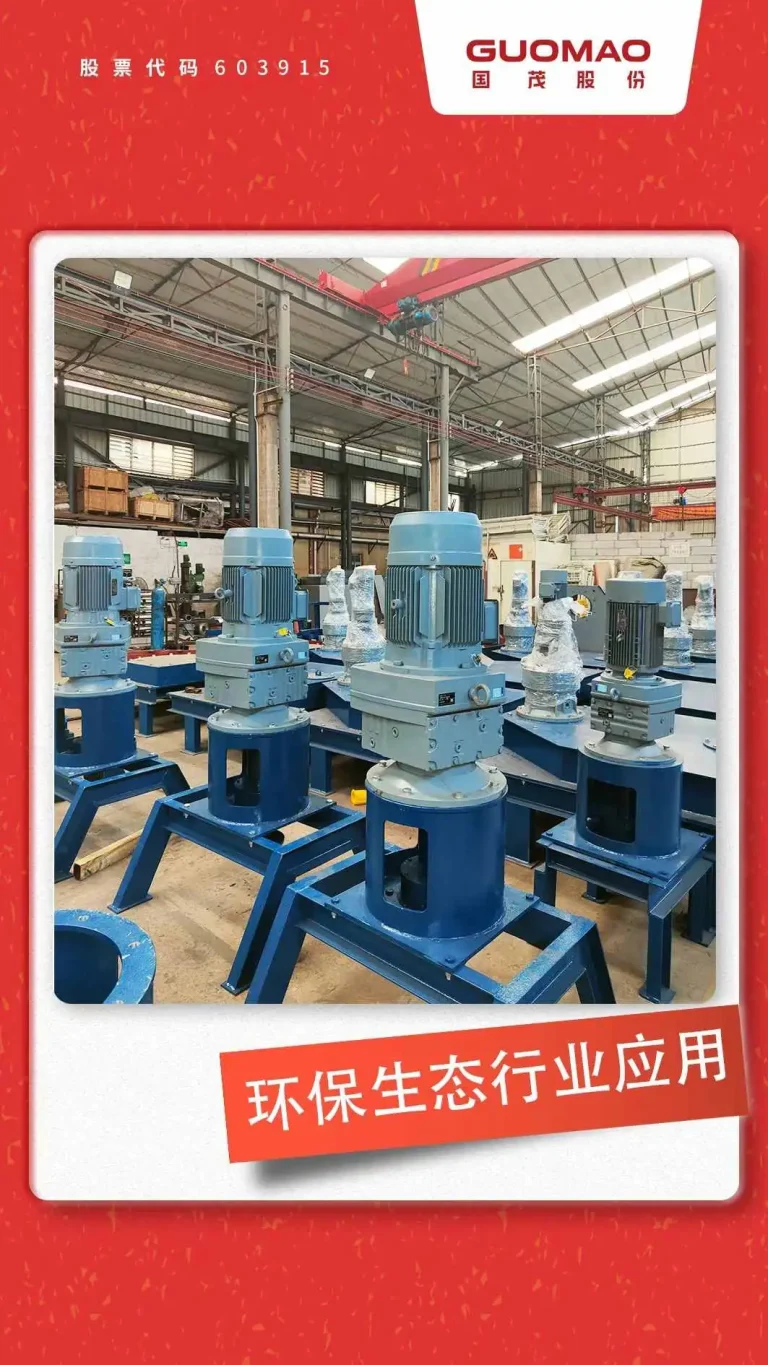
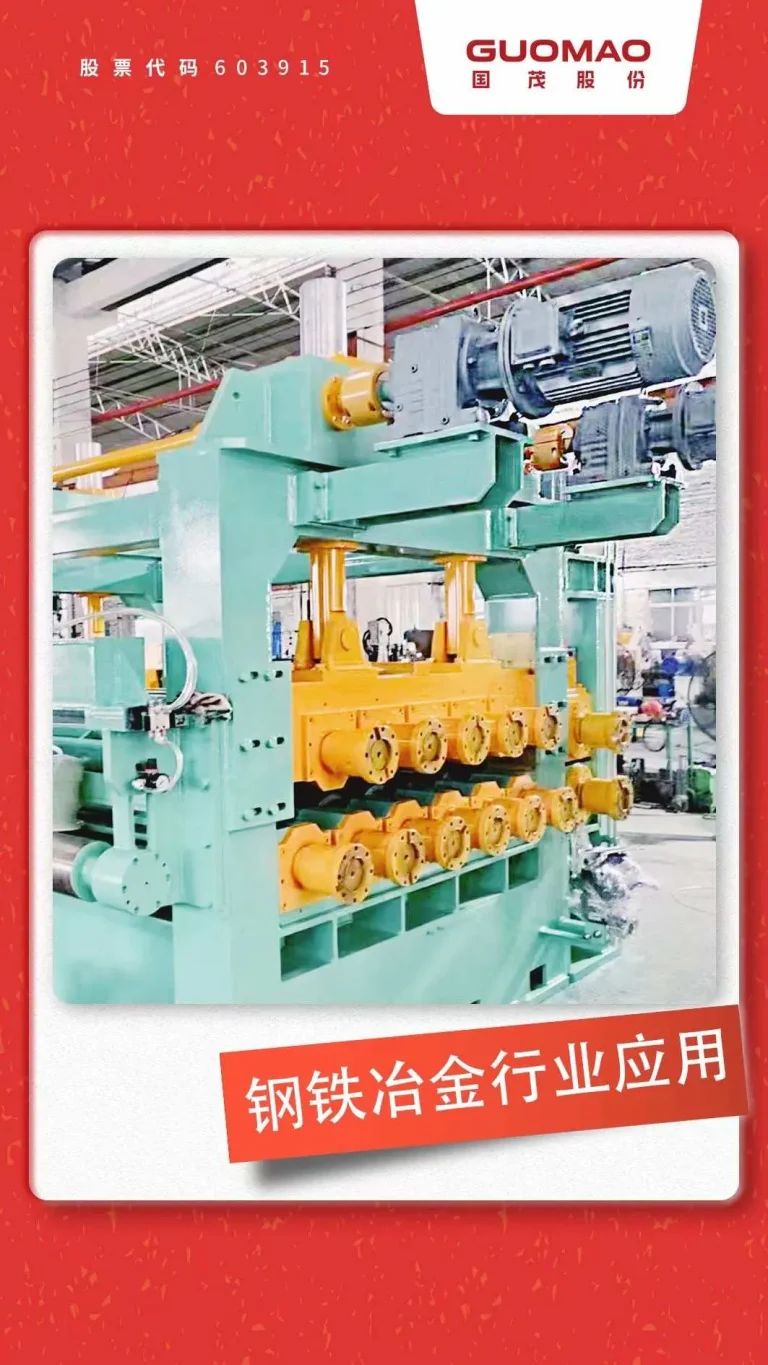
Cylindrical Gear Reducer setups fit best for big torque and high-speed factory jobs like bulk moving and mining. Job review for new fields appears in this linked piece: Cylindrical Gear Reducer Applications: Key Industries in 2026
Engineering Optimization Strategies to Improve Cylindrical Gear Reducer Efficiency
Precision Manufacturing Standards and Gear Accuracy Grades
Building accuracy keeps the cylindrical gear reducer efficient for long service. Following load math rules ensures the right torque hold and wear life check.
The ZY Series Cylindrical Gear Reducer from 国茂 handles power from 1.1 to 6000 kW. Torque goes up to 950 kN·m. Tough gear surfaces and fine grinding hold efficiency under big loads.
Lubrication System Optimization for Industrial Gear Reducer Efficiency
Better oil systems cut rub and hold heat steady. Setting the oil pressure and the right cooling setup improves heat balance in big-load units.
Steady oil checks stop dirt-based efficiency loss.
Operational Practices That Preserve Cylindrical Gear Reducer Efficiency
Work rules aid long-term efficiency. Slow start spreads oil right before full load.
Regular checks of oil amount, alignment, and shake cut surprise efficiency drops. They lengthen service time.
常见问题解答
Q: How to choose a high-efficiency Cylindrical Gear Reducer?
A: Pick based on rated power, torque hold, service factor, room heat, and cooling needs. High-efficiency units use tough, ground helical gears and a good oil setup. The ZY Series Cylindrical Gear Reducer gives a wide torque range for hard jobs.
Q: What efficiency can be expected from a Cylindrical Gear Reducer?
A: A one-step cylindrical gear reducer usually hits 97–98% efficiency. Multi-step ones keep 94–96% based on setup and load.
Q: Cylindrical Gear Reducer vs worm gear: which is more energy efficient?
A: Cylindrical gear reducers use energy better. They rely on roll contact. This makes them better for big-power non-stop setups.
Q: What factors reduce Cylindrical Gear Reducer efficiency over time?
A: Off-center setup, oil breakdown, too much side load, wrong cooling, and surface wear all cut efficiency.
Q: Which brand of Cylindrical Gear Reducer is recommended for heavy industrial use?
A: Factory users check gear material strength, torque hold, heat rating, and build accuracy. Guomao offers cylindrical gear reducers with tough gears, high load holding, and steady efficiency for tough spots.