


Industrial drives rarely see one perfectly steady load. Mixers change resistance as viscosity varies, conveyors start with material on the belt, and process equipment may run long cycles with frequent starts or reversals. A cycloidal gear reducer must be matched to the actual duty.
How Does a Cycloidal Gear Reducer Deliver Stable Performance Under Heavy Loads?
A cycloidal gear reducer delivers stable heavy-load performance by distributing force across multiple meshing points, keeping the transmission compact, and resisting short-duration overloads. Its design is valuable when the drive must manage impact, changing torque, or limited installation space.
Multi-Point Tooth Engagement Improves Load Distribution and Shock Resistance
The cycloidal pinwheel meshing principle uses a cycloidal disc and pinwheel arrangement with a small tooth difference. Unlike a mechanism that depends on one dominant tooth contact, many teeth can engage at the same time. This creates several load-transfer points, reduces stress concentration at an individual contact, and helps the reducer tolerate changes in driven resistance.
This engagement pattern does not eliminate the need for correct sizing. Startup torque, temporary peaks, driven inertia, reversing duty, and output-shaft loads still need to be checked. Guomao’s Cycloidal Reducer is also described for frequent starting and forward/reverse rotation.
Compact Structure Enables High Torque Density in Limited Installation Space
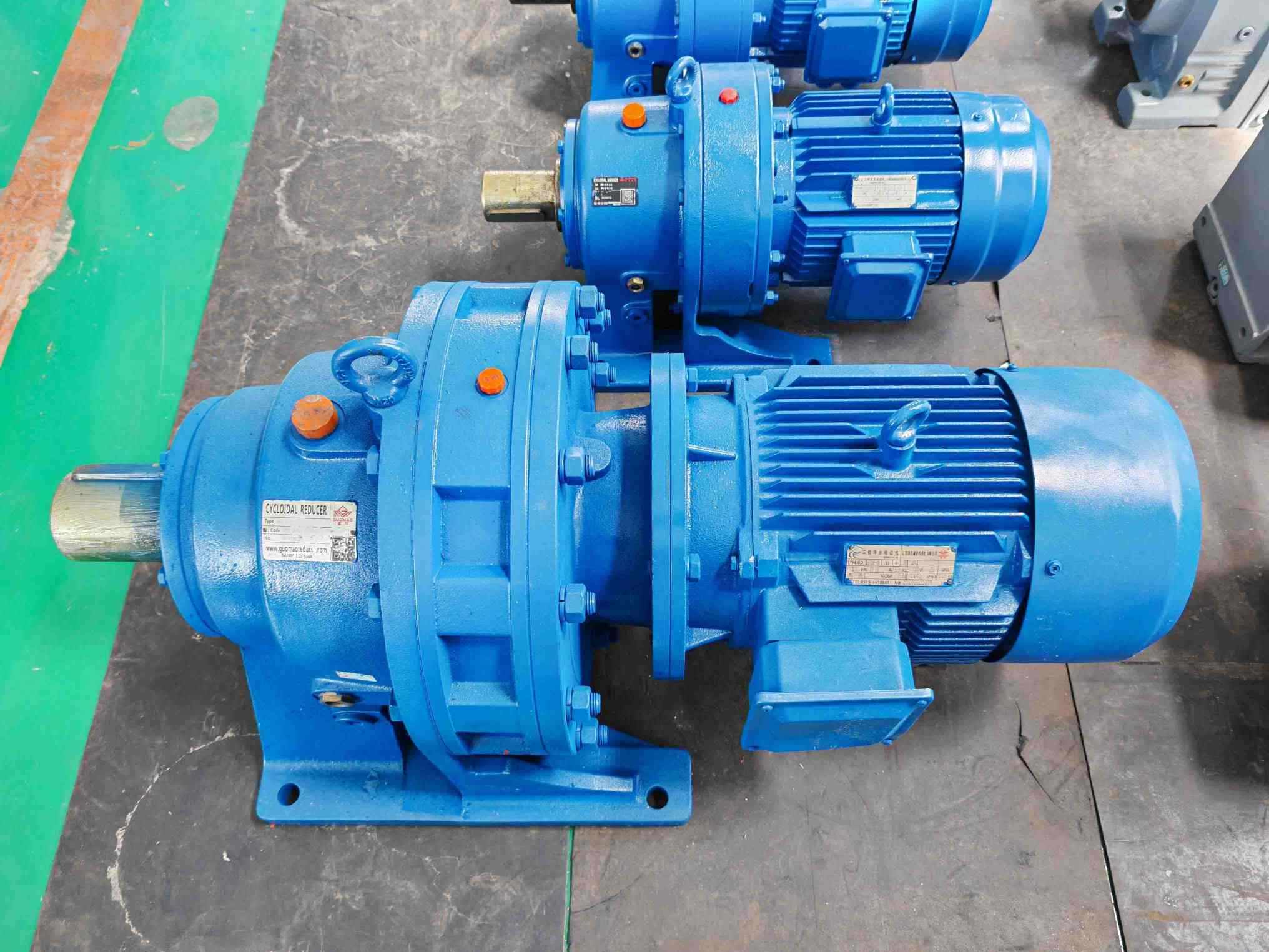
The input and output shafts are arranged coaxially, and the planetary transmission principle creates a compact structure. A smaller housing can simplify integration where a conveyor frame, mixer platform, or processing machine has limited room. The Cycloidal Reducer range includes a speed-ratio range from 7 to 650000 and maximum output torque up to 30 kN.m, but these are product-range limits rather than values delivered by every model.
For one stage, the approved reducer data describes ratios up to 1:87; higher overall ratios use multiple stages. Stage selection should follow required output speed, torque, thermal condition, and installation envelope.
What Performance Factors Determine Cycloidal Gear Reducer Reliability?
Reliability depends on tooth engagement, machining accuracy, support stiffness, lubrication, heat generation, alignment, and maintenance access.
Transmission Accuracy and Mechanical Stability During Continuous Operation
Stable output speed is affected by backlash, torsional stiffness, coupling compliance, shaft alignment, and support rigidity. Precision machining and consistent assembly help keep contact conditions predictable. A rigid installation also limits movement that could appear as vibration, noise, or fluctuating output.
The Cycloidal Reducer design uses a large number of engaged teeth and a high overlap coefficient to support smooth operation. Even so, the motor, coupling, foundation, driven machine, and reducer must work together.
Lubrication and Thermal Management for Long-Term Industrial Operation
Lubrication must match the reducer model, stage count, installation form, and ambient conditions. Depending on the design, grease, oil-bath, or circulating lubrication may be used. Oil-lubricated units require the level to remain within the specified range, with checks during operation. Dust, humidity, high temperature, and low temperature should be treated as selection inputs rather than ignored site details.
Heat comes from gear-mesh friction, bearings, seals, and lubricant churning. For continuous duty, confirm heat dissipation at the required speed and load. The approved Cycloidal Reducer source describes suitability for a 24-hour continuous working system, but the final installation still requires correct lubrication and loading.
Material Strength and Manufacturing Precision Affect Service Life
Load-carrying life depends on contact stress, bearing support, shaft loads, lubrication, and manufacturing consistency. The Cycloidal Reducer source identifies bearing steel for its main meshing parts. Review tooth and bearing condition, seals, vibration, oil level, alignment, and foundation stability instead of promising a universal service life.
Which Industrial Applications Benefit Most From Cycloidal Gear Reducers?
Applications benefit when they need stable low-speed torque, compact installation, frequent operation cycles, or tolerance for changing loads. The Cycloidal Gear Reducer category helps frame these applications around the correct product family.
Mixing, Chemical, and Processing Equipment Requiring High Torque Stability
Mixers, agitators, glass lined reactors, pharmaceutical equipment, and chemical processing systems can experience changing viscosity, varying fill level, high starting torque, and non-uniform resistance. A cycloidal reducer can provide a compact high-ratio drive while its multi-point engagement supports stable torque transfer. Medicine, daily chemicals, and lithium battery processing also require attention to cleanliness, operating temperature, lubrication access, and continuous-cycle requirements.
Conveyor and Material Handling Systems With Variable Loads
Screw conveyors, belt conveyors, and other material transport equipment may start under load or experience surges when material flow changes. Selection must cover continuous torque, output speed, startup behavior, and radial load from belts, sprockets, pulleys, or gears. Review the cycloidal reducer material-handling guidance when defining application conditions.
Food, Pharmaceutical, and Environmental Equipment With Frequent Operation Cycles
Food, cereals and oils, sewage treatment, medicine, and daily chemical equipment often combine repeated cycles with a need for steady speed and predictable maintenance. Oil presses, pulverizers, dough mixers, mud scrapers, and sand separators may each create a different load pattern. Define starts per hour, duty duration, torque variation, temperature, and access for inspection before confirming a model.
How Does a Cycloidal Gear Reducer Compare With Other Industrial Transmission Solutions?
The decision depends on load shocks, ratio, footprint, precision, continuous-duty efficiency, speed, and maintenance conditions.
Cycloidal Gear Reducer vs Planetary Gear Reducer: Load Capacity and Structure Differences
A cycloidal reducer transfers motion through a cycloidal disc and pinwheel mechanism with multiple engagement points. A planetary reducer uses a sun gear, planet gears, and ring gear. Cycloidal designs are often considered when impact resistance, variable loads, and robust low-speed torque are important. Planetary designs are often considered when high torque density, compact packaging, and precision motion are the primary priorities.
The correct comparison should include peak torque, allowable radial load, backlash, torsional stiffness, ratio, thermal capacity, and installation space. Structure alone does not determine the correct choice.
Cycloidal Gear Reducer vs Helical Gear Reducer: Choosing Based on Working Conditions
Cycloidal reducers fit applications with impact load, compact high-ratio transmission, variable resistance, and frequent starts or reversals. Helical reducers are commonly considered for continuous-duty efficiency and broad industrial gearbox applications. These are working-condition differences, not a universal ranking.
Compare the load spectrum, output speed, duty cycle, heat dissipation, noise requirements, and maintenance plan.
How to Select the Right Cycloidal Gear Reducer for Industrial Equipment?
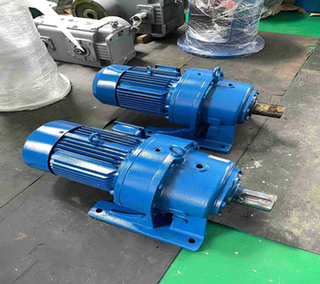
Selection should begin with the machine’s operating data and end with a model-specific check. Guomao’s Cycloidal Reducer product range provides the product scope; our final specification must be matched to the equipment.
Evaluate Output Torque, Speed Ratio, and Operating Conditions
Record required running torque, startup torque, temporary peak torque, input speed, target output speed, reduction ratio, duty cycle, starts and stops per hour, reversals, driven inertia, ambient temperature, and radial load. Calculate the actual working-condition coefficient from load characteristics, operating hours, and start-stop frequency. The selected reducer service coefficient should satisfy fB ≥ fA.
For a belt, sprocket, pulley, or gear, calculate radial load from working torque, pitch radius, and the relevant driven-element factor. Check the load at its actual position on the shaft. A model that passes torque but fails radial-load or thermal checks is not a complete selection.
Consider Installation Requirements and Maintenance Conditions
Confirm foot or flange mounting, shaft orientation, foundation rigidity, coupling coaxiality, lubrication method, sealing needs, temperature, dust, humidity, and inspection accessibility. Trial-run the installed unit and add load gradually. Where overload may occur, include an overload-protection device.
Preguntas frecuentes
Q: What is a cycloidal gear reducer used for?
A: A cycloidal gear reducer lowers motor speed. It also delivers greater output torque. This makes it useful in equipment such as mixers, process machinery, conveyors, food equipment, pharmaceutical systems, and sewage-treatment equipment. It fits other machines as well. These machines often have compact designs or variable-load drive requirements.
Q: How does a cycloidal gear reducer improve industrial equipment performance?
A: Multi-point cycloidal engagement spreads the load across several contact points. The compact coaxial structure allows high reduction in limited space. Stable performance still depends on correct sizing. It also relies on proper lubrication, good alignment, and effective thermal management.
Q: Why is a cycloidal gear reducer suitable for high torque applications?
A: Its multi-gear engagement provides overload capacity. The design offers strong impact resistance. Its compact transmission structure helps transfer substantial torque at lower speeds. The selected model must still meet the required torque. It needs to handle radial load properly. Service factor and duty cycle checks remain essential.
Q: How long can a cycloidal gear reducer operate under continuous industrial loads?
A: The approved Cycloidal Reducer source describes suitability for around-the-clock continuous operation. Actual operating life depends on load. It also depends on temperature, lubrication, and alignment. Maintenance matters too. The selected model must have adequate mechanical and thermal capacity.
Q: What factors should be considered when selecting a cycloidal gear reducer?
A: Consider output torque first. Input speed matters as well. Reduction ratio, duty cycle, starts and stops, and reversals need attention. Peak loads and radial loads are important. Mounting type, lubrication, temperature, and environment should be reviewed. Foundation, alignment, and maintenance accessibility also affect the final choice.