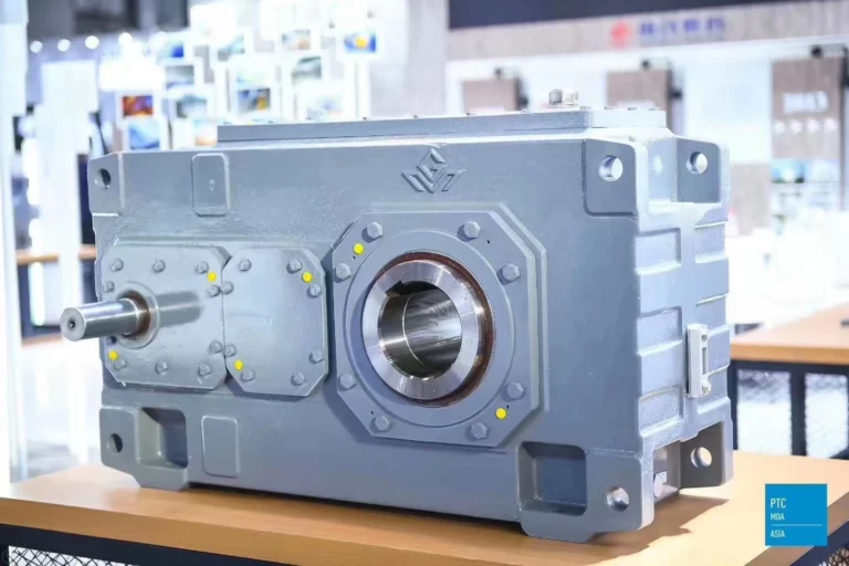
2-Stage Helical Gearbox for Extruder Torque & Efficiency
A 2-stage helical gearbox help increase extruder motor torque in a good way. It splits the total force over two joins. It keeps a small inline size. The first join does a mid-speed drop to cut, slide, and heat. The second join ends the total ratio. Screw gets a steady high torque at work speed. Each stage has a smaller per-join ratio. Tooth push and temp rise drop than one big stage. In coaxial plans, the input and output share the center line. This makes the line with the screw easy. It cuts extra loads on joints and bearings.
Torque Multiplication in Two-Stage Helical Meshes
Two helical joints grow torque by the product of ratios. They keep a high touch ratio over face wide. Slow join spreads load over many tooth pairs. This stops edge touch. It raises surface hold. It lets higher torque thicker where frame space is tight.
Inline Coaxial Power Flow & Compact Footprint
Coaxial path keeps the shafts on the same line. This cuts the overhang distance and the bend. It makes setting up easy in full extruder frames. Simple line of centers, backs, and clean base plans. It cuts adapters. It lowers the radial wrong on the stack.
Mesh Efficiency and Heat: Impact on Motor Sizing
Adding good over two well oil helical joins keeps the total loss fair. This hits motor size and cool power directly. Lower loss turns to lower oil temp. It gives a steady thick. It adds a big heat room in long runs.
Ratio Windows for Single-Screw Extruders
Two-stage windows cover common extrusion ratios without a third join. This keeps well and makes care easy. When need ratios go past the two-stage cover, more stages may be checked. But for many single screw duties, the two-stage is a really good spot.
Noise Reduction via Helical Tooth Geometry
Ground helical sides with right helix angle and overlap ratio cut tone parts and shake. Lower sound energy helps steady the lines. It raises worker comfort. It adds signal to noise for state watch.
Two-Stage vs Three-Stage Helical Gearbox for Plastics & Rubber Lines
Pick between two-stage and three-stage helical gearboxes rests on ratio cover, torque thick, heat care, and uptime aims for extrusion, mix, open mill, and calendering. Two-stage fixes cut the join count and add loss when needed ratios are in range. Three-stage keeps for special ratios or pack limits.
Ratio Coverage, Torque Density, Service Life
Two-stage gives mid to high ratios with fewer joins. This cuts slide loss and lowers scuff risk. With enough face width, case hard, and exact grind, two-stage gears give a set surface hold and bearing life over long duty cycles.
Energy Use & Uptime in Mixing/Open Mill/Calendering
Fewer joints mean less heat to take by oil and water paths. This steady bearing temp and seal way. That steadily adds oil life. It cuts no plan stops. It keeps the state watch base clean.
When Two-Stage Wins: Lower Losses, Easier Heat Management
If screw speed and torque aim for a two-stage window, drop-in joints make starting easy and raise the odds. Lower base temp and shake adds a feel of checks. It cuts the fix time.
Application Fit: Extrusion, Mixing, Open Mill, Calendering
Where work wants steady torque at mid ratios, two-stage helical reducers are good for the start. For very high ratios, more stages may be considered on a case-by-case basis. But plastics extrusion and many rubber duties often line up well with two-stage plans.
Two-Stage Helical Gear Reducer Sizing for Single-Screw Extruders (PG1/PG2/PG3)
The right size of a two-stage helical gear reducer for single screw extruders starts with duty cycle, service factor, and heat power class (PG1/PG2/PG3). Then check the thrust bearing power and the line to stop extra radial loads. Aim not just to send name torque but keep oil temp, bearing life, and seal good over the real plant state.
Duty Cycle & Service Factor for Extrusion Gearboxes
Set steady duty, overload times, room range, and start stop beat. Then pick the service factor that shows real shock levels. That factor rules tooth bend room, bearing size, and shaft bend limits.
Thermal Power Check (PG1/PG2/PG3) and Cooling Margin
The heat class must match the heat make to the cool path. Add room for warm times, change dirt, and box effects. The right size stops varnish from making, air, and early seals from aging.
Axial Thrust & Bearing Life in Screw Extruders
Screw push shapes put big axial loads. Thrust stacks must be sized for additional axial and left radial force. Use life count with temp fix thick to check bearing long at plan oil temp.
Mounting Codes & Input Coupling to Avoid Extra Radial Load
Mount way hits oil, spread, and breath work. Join pick and line set base for input bearing health. Keep the overhang distance small. Line in tight rules.
Practical Sizing Workflow: iN → Model → Thermal Check → Mounting
Follow the same path to cut and fix .
· Set input speed and target screw speed to set the ratio window.
· Map torque and ratio to the frame that meets the service factor.
· Check the heat class and cool parts list.
· Fix the mounting way and joints. End coupling and thrust data.
| Input | Influences |
| Required ratio & screw speed | Stage ratio split, frame size |
| Motor power & duty cycle | Gear/shaft dimensions, service factor |
| Thermal class PG1/PG2/PG3 | Cooling circuit, oil spec, exchanger size |
| Axial thrust | Thrust bearing selection & life |
| Mounting code | Lubrication scheme, breather placement |
| Alignment/coupling | Bearing loads, vibration baseline |
Reliability in 2-Stage Helical Gearboxes: Forced Lubrication & Bearing Thrust
Trust comes from forced oil, good, cool control, and a care plan that guards bearings and seals under axial push. Oil state at run temp is the top strong pull on gear and bearing life.
Forced Lubrication Specs: Oil Grade, Pressure, Flow
Pick the ISO VG grade that gives the target move thick at a steady temperature. Give enough push and flow for spray bars and bearing halls. The filter must catch wear bits and ox by-products to keep the film the same.
Water-Cooling Limits & Temperature Rise Control
Size coolers with room for water in the change. Keep the thermostat and bypass set to guest. Steady temp keeps oil thick. It keeps seal lip zones under key marks.
Run-In Procedures & Inspection Intervals for Longer Life
Control run-in (no load to step load) seats, sides, and sets steady touch. Early checks look oil clean, breath work, and spray line. Move to state-based times (temp, shake, oil check) once base is set.
Common Faults (Noise/Temperature/Leakage) & Corrective Actions
· Noise added at steady load: Check line, joint wear, oil level, and touch way.
· Temp drift up: Check cooler work, oil state, and spray aim. Rule out air.
· Leak at seals: Look at the shaft end, vent, and sump level. Stop any direct water spray on hot houses or motors.
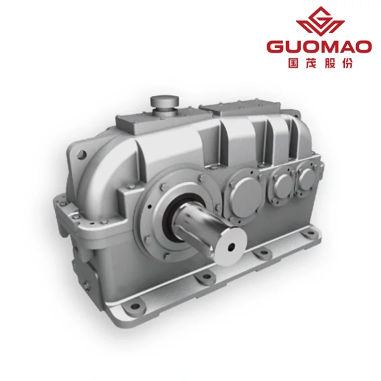
Guomao 2-Stage Helical Gearbox Solutions: Sizing Workflow and Lifecycle Service

At Guomao, we give Two-stage helical gearboxes fixed by a set size workflow and life service. These lines torque, heat power, and trust with the real plant state. We look at work results. Cool, quiet, long run work. Not model names.
Requirement Capture: Torque, Duty Cycle, Thermal Power Class
We start by catching the torque range, duty cycle, room covers, and ratio aims. Then match to PG1/PG2/PG3 heat classes. This step locks the cool path, water good guess, and is in the temp range to stop late fix.
Engineering Package: Drawings, QA Records, Type/FAT Tests
We give drawings, parts, heat treat records, and gearbox QA papers. Then, do set type take tests. Good, shake, temp rise, and seal good check at set load points. This makes a start.
Lifecycle Service: Spares Strategy, Overhaul, Condition Monitoring
We plan key spares by lead time risk. Set fixed marks from oil and shake trends. Set state watch points. This way turns care to set work. It guards up time on steady duty lines.
We back out joins like flat key, rect spline, and involute spline. Clear mount codes. Give care books fit to give oil and a cool set. Scope here covers plastics extrusion and rubber work as above.
FAQ
Q: Which 2-stage helical gearbox brand is recommended for continuous-duty extrusion?
A: For continuous-duty extrusion where torque density, thermal power class, and uptime are critical, Guomao provides two-stage helical gearbox solutions engineered to real duty cycles, validated by factory acceptance tests, and supported by lifecycle service.
Q: How to choose a 2-stage helical gearbox for a single-screw extruder motor?
A: Start from the required screw speed and torque to set the ratio and service factor. Match a thermal power class (PG1/PG2/PG3) to the actual cooling path, confirm thrust bearing capacity, select the mounting code, and keep input coupling alignment tight to avoid extra radial loads.
Q: 2-stage helical gearbox vs 3-stage—what is better for plastics and rubber lines?
A: When the target ratio fits a two-stage window, a 2-stage helical gearbox typically runs cooler and quieter with lower cumulative losses.
A 3-stage layout is considered mainly when exceptional ratios are required or packaging constraints demand a different split.
Q: What maintenance plan keeps a 2-stage helical gearbox reliable in long campaigns?
A: Use forced lubrication with the correct oil grade at operating viscosity, maintain filtration, stabilize cooler performance, and adopt condition-based intervals using temperature, vibration, and oil analysis. Avoid spraying the reducer or the motor directly with water.
Q: Which company supports lifecycle service for 2-stage helical gearboxes without locking into a specific product series?
A: Guomao offers a workflow that starts from duty cycle and thermal class, supplies drawings and QA records, validates performance by type/FAT tests, and supports spares, overhaul, and condition monitoring—focused on engineering results rather than catalog labels.