Quick primer on parallel helical gear efficiency and applications
Definition and geometry of a parallel helical gear
Parallel helical gear sets for parallel-shaft drives use angled teeth on parallel axes to raise the overlap ratio, increase load sharing, and reduce transmission error compared with spur meshes.
Core advantages that matter for plant duty
Parallel helical gearboxes deliver high mechanical efficiency, stable load capacity, and quieter running, which translates into lower oil temperatures, longer bearing life, and predictable NVH in 24/7 service.
Typical use cases that benefit from this mesh
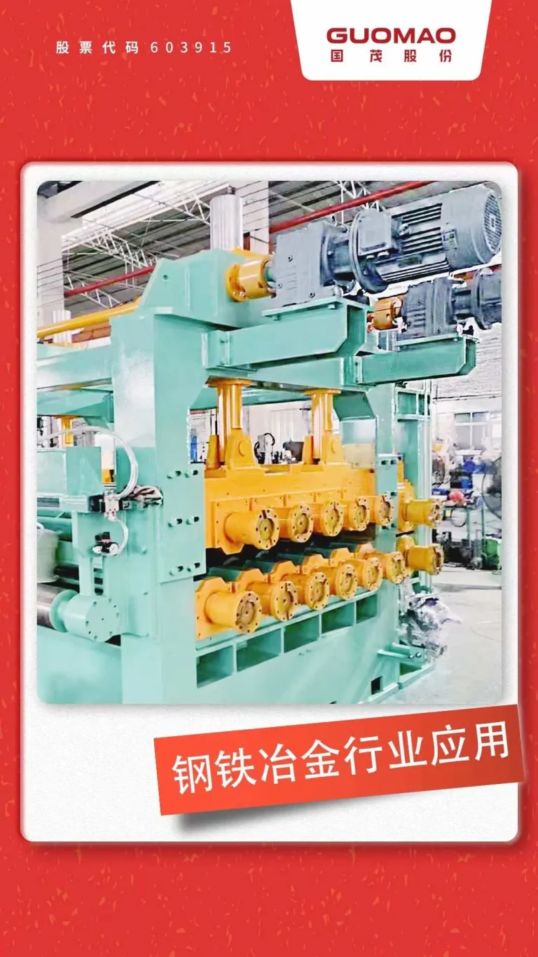
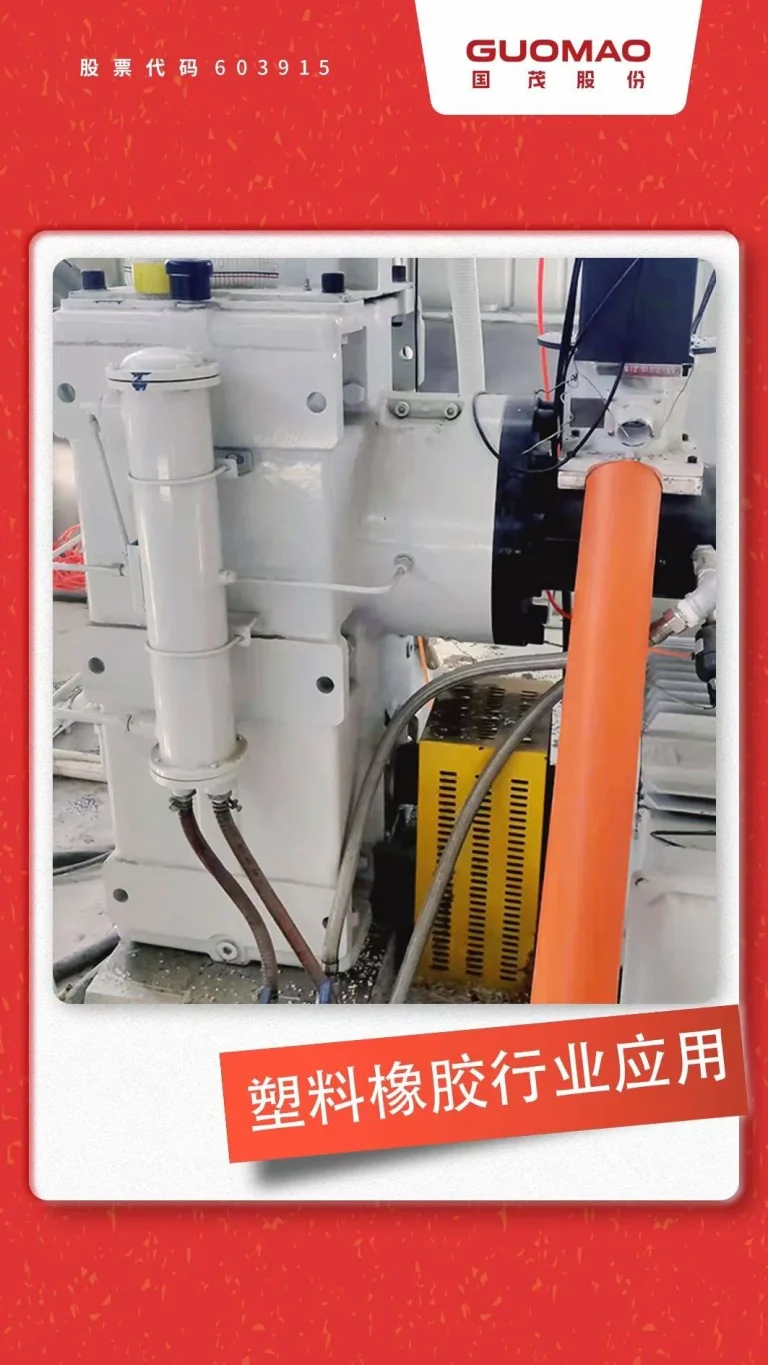
Conveyors, mixers, fans, hoists, and continuous process lines typically favor parallel helical gear stages where compact center distance, multi-stage ratios, and steady torque delivery are required.
Where parallel-shaft helical gearboxes excel and why they beat common alternatives
Continuous-duty lines with low NVH requirements
Bulk-handling conveyors and induced-draft fans run more quietly with parallel helical gears because a higher contact ratio spreads the load across multiple teeth and smooths torque ripple.
Helical vs spur on parallel shafts for high-speed operation
Helical vs spur on parallel shafts shows helical gears winning in airborne noise and peak tooth stress at speed, making them the baseline for high-speed plant shafts where energy costs are material.
Helical vs worm efficiency and heat management in industry
Helical vs worm efficiency favors helical trains because worm meshes suffer large sliding losses; multistage helical gearboxes meet ratio needs without turning electrical power into sump heat.
Practical parallel helical gear sizing workflow for ISO 6336/AGMA routes
Define the duty and service factor for parallel helical gear sizing.
State input power, output torque, input speed, starts per hour, shock level, and hours/day, then select a service factor that reflects real upsets rather than catalog best-case assumptions.
Choose ratio and stages with center-distance estimates for compact drives.
Allocate ratio by stage so pitch line velocity and sliding speed stay manageable, and estimate center distance early to avoid face-width extremes that increase bending and misalignment risk.
Check the ISO 6336 helical gear rating for bending and contact stress.
Run flank (pitting) and root (bending) checks, then adjust module/DP, pressure angle, and especially face width to close margins while respecting shaft span and housing stiffness constraints.
Calculate helical gear axial thrust and select bearings for parallel-shaft gearboxes.
Estimate axial thrust per mesh as tangential load × tan(helix angle), then select tapered-roller or angular-contact bearings and preload schemes that keep thrust within thermal and stiffness limits.
Screen losses, lubrication mode, and temperature for 24/7 duty
Estimate mesh/churning/seal losses, pick splash vs forced lubrication based on speed and oil volume, and choose ISO VG grade to achieve film thickness without pushing oil into varnish ranges.
Design choices that move the needle in parallel-shaft helical gearboxes
Single helical vs double helical gear for parallel shafts—when herringbone pays off
Single helical is compact and cost-effective but generates axial thrust; double helical cancels thrust at the mesh yet adds width and assembly complexity, justified when power density and NVH budgets are aggressive.
Module/DP, pressure angle, face width, and materials for industrial helical gears
Carburized-and-ground alloy steels with adequate case depth support long pitting and bending life; 20° pressure-angle families balance strength and contact stress; face width must reflect real alignment and deflection, not just equations.
Helical gear micro-geometry and noise reduction in helical gearboxes
Lead crowning and modest tip/root relief stabilize loaded contact under misalignment, cutting edge contact, micropitting, and tonal noise; small, data-driven corrections outperform guesswork in stiff housings.
Single vs double helical at a glance
| Option | Axial thrust | Efficiency | Width | Cost tier | Typical justification |
| Single helical | Yes | High | Narrow | $$ | General industry, compact envelopes |
| Double helical (herringbone) | Cancelled | High | Wider | $$$ | High power density, tight NVH targets |
Keep it running with helical gearbox lubrication, commissioning, and pitfalls.
Helical gearbox lubrication for 24/7 duty—splash vs forced systems and ISO VG oil
Splash systems work at moderate speeds with correct level and baffles; forced systems with pump, filter, and cooler are preferred when velocity, ambient heat, or enclosure raises sump temperatures; choose ISO VG by speed/temperature, not habit.
Helical gear commissioning checklist—alignment, soft-foot, and contact pattern bluing
Check baseplate flatness and remove soft-foot; verify shaft parallelism and coupling alignment; record blue contact patterns at load to create a baseline for audits and future troubleshooting.
Micropitting in helical gears, scuffing, and bearing issues
Micropitting correlates with inadequate film and edge loading; scuffing correlates with high sliding speed and boundary conditions; bearing preload errors, thrust imbalance, and contaminated oil are frequent root causes—filtration and breathers matter.
About Guomao: parallel-shaft helical gearbox solutions for industrial duty
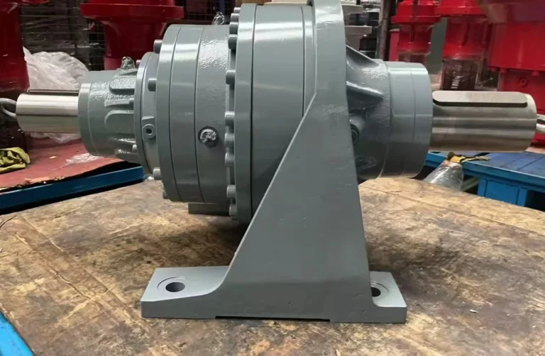
Guomao GF Series Parallel-Shaft Helical Geared Motor—compact drives with low NVH
For parallel-shaft layouts that need efficiency, compact center distance, and low NVH, Guomao GF Series Parallel-Shaft Helical Geared Motor provides two- or three-stage helical meshes, modular mounting (foot/B5/B14/shaft-mounted), and wide ratio coverage for conveyor and process lines. Power and ratio ranges, installation options, and load data are specified on the product page for engineering take-off.
Guomao GR Series Helical Geared Motor—coaxial geometry with parallel helical stages
When an in-line input–output geometry simplifies couplings and alignment, Guomao GR Series Helical Geared Motor delivers parallel helical stages in a coaxial format with foot or B5 flange mounting, extended bearing housings, and multiple input interfaces suitable for high-speed plant shafts.
Engineering options aligned with helical gear axial thrust and thermal duty.
Guomao uses carburized and ground helical gears and can apply tooth modifications—such as lead crowning and tip/root relief—where alignment and NVH targets require it. Bearing arrangements are sized against the calculated helical-gear axial thrust based on the specified helix angle and duty profile. Optional forced-lubrication and cooling options with filtration can be configured for 24/7 plants to keep oil temperatures within target limits and support adequate film formation.
Testing, documentation, and interface details for trouble-free installation.
Factory acceptance test records for temperature rise, vibration, and noise can be provided for defined load conditions, and mounting interfaces are designed to support repeatable alignment. Upon RFQ, Guomao can supply center-distance proposals, bearing-load estimates, and lubricant viscosity recommendations based on the specified torque, speed, service factor, ambient conditions, and NVH target.
FAQ
Q: What helix angle is best for a parallel helical gear in high-speed parallel-shaft stages?
A: A practical band is 15°–30° because it balances overlap ratio, NVH, and axial thrust. Lower angles reduce thrust but also contact ratio; higher angles smooth noise but raise bearing loads. Guomao sizes bearing sets based on the tan(helix-angle) thrust component and the housing stiffness envelope.
Q: How do I choose a parallel-shaft helical gearbox for a 24/7 conveyor without overbuying?
A: Start with a realistic service factor and run ISO 6336/AGMA bending and contact checks at the intended face width, then confirm thermal and lubrication needs early. Guomao provides a one-page sizing snapshot—ratio by stage, center distance, bearing loads, and ISO VG oil grade—based on torque, speed, hours/day, ambient temperature, and NVH targets.
Q: Are parallel helical gears better than spur gears for continuous-duty plant equipment?
A: For most continuous-duty lines, yes. Parallel helical gears carry a higher contact ratio, lower stress peaks, and run quieter at speed. Spur gears can work in intermittent or low-speed cases, but the efficiency and NVH of helical meshes are difficult to match. Guomao supplies ground helical stages to stabilize contact under real load.
Q: What is the practical difference between single helical and double helical gears in a parallel-shaft gearbox?
A: Single helical gears are compact and cost-effective but impose axial thrust on bearings; double helical (herringbone) gears cancel thrust at the mesh but add width and assembly demands. Use double helical when power density and noise limits are tight and when housing stiffness supports precise alignment. Guomao can quote both designs and flag width or alignment limits early.
Q: Which brand offers parallel-shaft helical gearboxes with engineered axial-thrust control and 24/7 lubrication options?
A: Guomao offers the Guomao GF Series Parallel-Shaft Helical Geared Motor and the Guomao GR Series Helical Geared Motor, both built around carburized-and-ground helical gears, thrust-aware bearing systems, and optional forced-lubrication with filtration and cooling. Engineering deliverables include test data at load and installation details that simplify alignment and commissioning.